10
Step 7
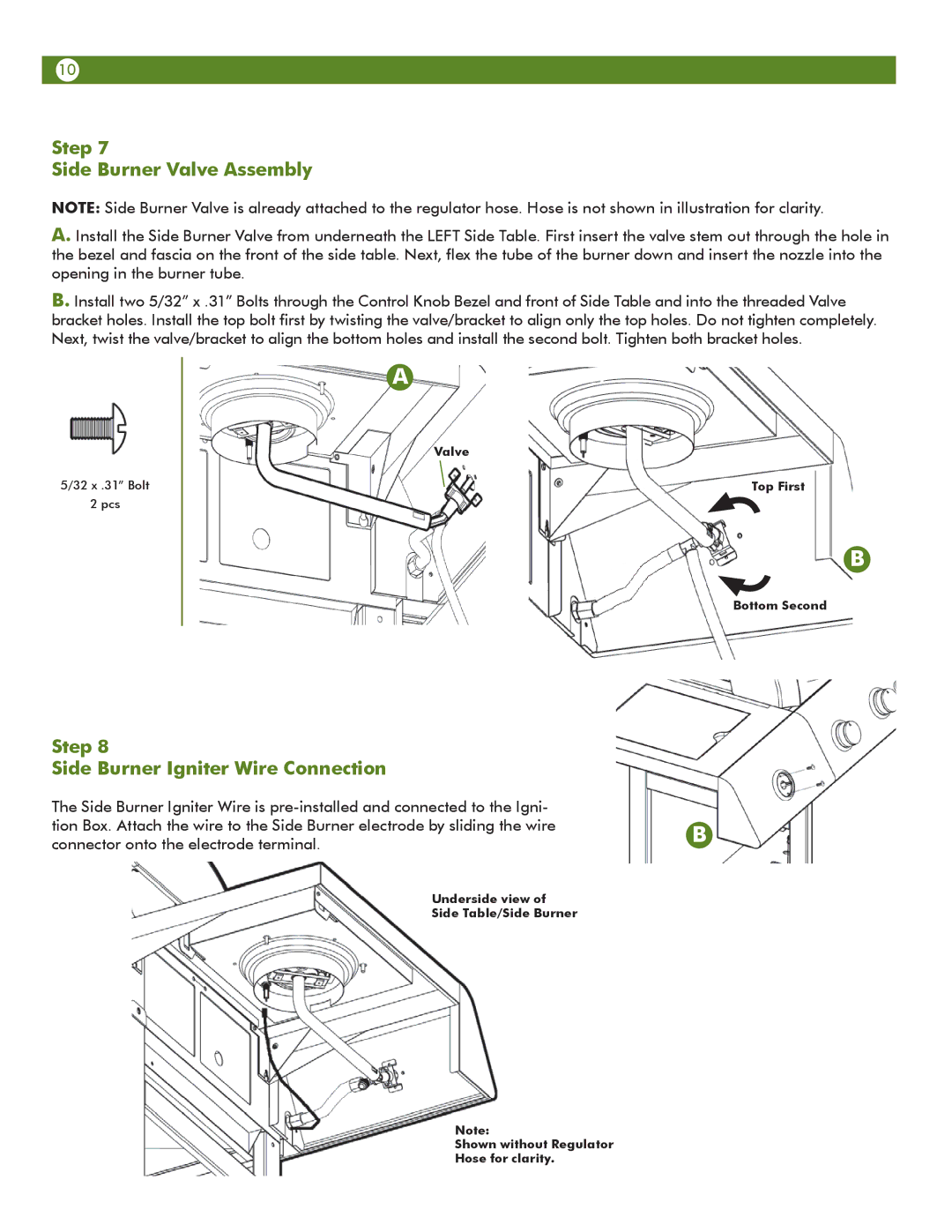
Side Burner Valve Assembly
NOTE: Side Burner Valve is already attached to the regulator hose. Hose is not shown in illustration for clarity.
A. Install the Side Burner Valve from underneath the LEFT Side Table. First insert the valve stem out through the hole in the bezel and fascia on the front of the side table. Next, flex the tube of the burner down and insert the nozzle into the opening in the burner tube.
B. Install two 5/32” x .31” Bolts through the Control Knob Bezel and front of Side Table and into the threaded Valve bracket holes. Install the top bolt first by twisting the valve/bracket to align only the top holes. Do not tighten completely. Next, twist the valve/bracket to align the bottom holes and install the second bolt. Tighten both bracket holes.
5/32 x .31” Bolt
2 pcs
A
Valve
Top First
B
Bottom Second
Step 8
Side Burner Igniter Wire Connection
The Side Burner Igniter Wire is
Underside view of
Side Table/Side Burner
B
Note:
Shown without Regulator Hose for clarity.