9
!CAUTION
Prior to performing any further assembly, PERFORM “FIRST TIME USE” LEAK TEST as detailed on pages
If the grill is fully assembled before performing the First Time Use leak test, the side tables will need to be removed in order to perform the leak test on the main burner valves inside the control panel, behind the knobs, .
Step 6
Side Table Assembly
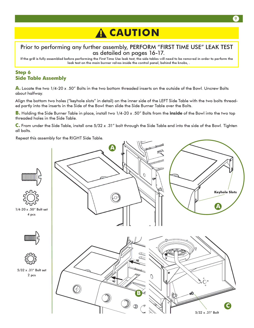
A. Locate the two
Align the bottom two holes (“keyhole slots” in detail) on the inner side of the LEFT Side Table with the two bolts thread- ed partly into the inserts in the Side of the Bowl then slide the Side Burner Table over the Bolts.
B. Holding the Side Burner Table in place, install two
C. From under the Side Table, install one 5/32 x .31” bolt through the Side Table end into the side of the Bowl. Tighten all bolts.
Repeat this assembly for the RIGHT Side Table.
A
Keyhole Slots
4 pcs
5/32 x .31” Bolt set
2 pcs
A
B
C
5/32 x .31” Bolt