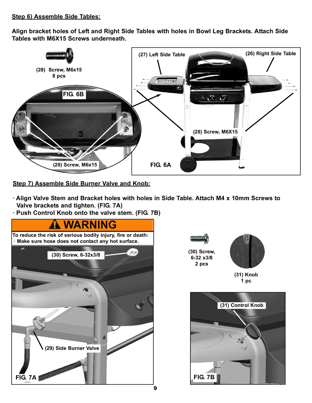
Step 6) Assemble Side Tables:
Align bracket holes of Left and Right Side Tables with holes in Bowl Leg Brackets. Attach Side Tables with M6X15 Screws underneath.
(27) Left Side Table | (26) Right Side Table |
(28)Screw, M6x15 8 pcs
FIG. 6B
(28) Screw, M6X15
(28) Screw, M6x15 | FIG. 6A |
Step 7) Assemble Side Burner Valve and Knob:
·Align Valve Stem and Bracket holes with holes in Side Table. Attach M4 x 10mm Screws to Valve brackets and tighten. (FIG. 7A)
·Push Control Knob onto the valve stem. (FIG. 7B)
To reduce the risk of serious bodily injury, fire or death: · Make sure hose does not contact any hot surface.
(30) Screw,
![]() (29) Side Burner Valve
(29) Side Burner Valve
FIG. 7A
9
(30)Screw,
2 pcs
(31) Knob
1 pc
(31) Control Knob
FIG. 7B