Hardware Setup
Front Panel Connector: JFP1 or JFP2
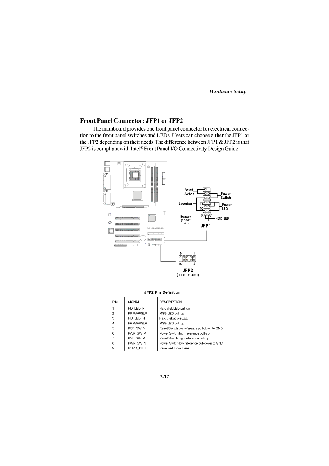
The mainboard provides one front panel connector for electrical connec- tion to the front panel switches and LEDs. Users can choose either the JFP1 or the JFP2 depending on their needs.The difference between JFP1 & JFP2 is that JFP2 is compliant with Intel® Front Panel I/O Connectivity Design Guide.
Reset
SwitchPower
![]() Switch
Switch
Speaker | 11 |
| Power |
| 10 |
| LED |
Buzzer | 8 |
| 1 |
|
| HDD LED | |
(short |
| + | |
pin) | JFP1 |
| |
|
| ||
|
|
|
|
|
|
|
|
|
|
|
|
|
|
|
|
|
|
|
|
|
|
|
|
|
|
|
|
|
|
|
|
|
|
|
|
|
|
|
|
|
|
|
|
|
|
|
|
|
|
| 9 |
| 1 | |||
|
|
|
|
|
|
|
|
|
|
|
|
|
|
|
|
|
| 2 |
|
|
|
|
|
|
|
|
|
|
|
|
|
|
|
|
|
| |
|
|
|
|
|
|
|
|
|
|
|
| 10 | ||||||
|
|
|
|
|
|
|
|
|
|
|
|
|
|
|
|
| JFP2 |
|
|
|
|
|
|
|
|
|
|
|
|
|
|
|
| (Intel spec) | |||
|
|
|
|
|
|
| JFP2 Pin Definition |
| ||||||||||
|
|
|
|
|
|
|
|
|
|
|
|
|
|
| ||||
PIN |
| SIGNAL | DESCRIPTION |
| ||||||||||||||
1 |
|
|
|
| HD_LED_P | Hard disk LED |
| |||||||||||
2 |
|
|
|
| FP PWR/SLP | MSG LED |
| |||||||||||
3 |
|
|
|
| HD_LED_N | Hard disk active LED |
| |||||||||||
4 |
|
|
|
| FP PWR/SLP | MSG LED |
| |||||||||||
5 |
|
|
|
| RST_SW_N | Reset Switch low reference | ||||||||||||
6 |
|
|
|
| PWR_SW_P | Power Switch high reference | ||||||||||||
7 |
|
|
|
| RST_SW_P | Reset Switch high reference | ||||||||||||
8 |
|
|
|
| PWR_SW_N | Power Switch low reference | ||||||||||||
9 |
|
|
|
| RSVD_DNU | Reserved. Do not use. |
| |||||||||||