Installing the Digital Controller
Step | Procedure |
1. | Insert the Digital Temperature Controller into the same panel slot making sure the face of the controller |
| is upright with the display on top and the push buttons on the bottom. |
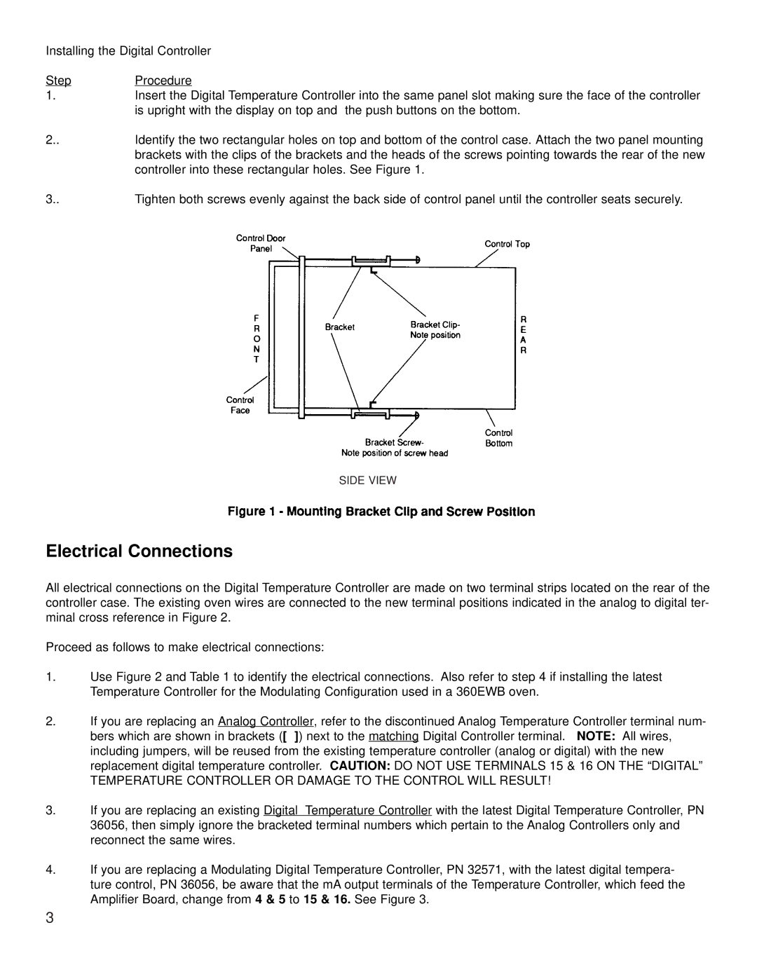
2.. | Identify the two rectangular holes on top and bottom of the control case. Attach the two panel mounting |
| brackets with the clips of the brackets and the heads of the screws pointing towards the rear of the new |
| controller into these rectangular holes. See Figure 1. |
3.. | Tighten both screws evenly against the back side of control panel until the controller seats securely. |
SIDE VIEW
Electrical Connections
All electrical connections on the Digital Temperature Controller are made on two terminal strips located on the rear of the controller case. The existing oven wires are connected to the new terminal positions indicated in the analog to digital ter- minal cross reference in Figure 2.
Proceed as follows to make electrical connections:
1.Use Figure 2 and Table 1 to identify the electrical connections. Also refer to step 4 if installing the latest Temperature Controller for the Modulating Configuration used in a 360EWB oven.
2.If you are replacing an Analog Controller, refer to the discontinued Analog Temperature Controller terminal num- bers which are shown in brackets ([ ]) next to the matching Digital Controller terminal. NOTE: All wires, including jumpers, will be reused from the existing temperature controller (analog or digital) with the new replacement digital temperature controller. CAUTION: DO NOT USE TERMINALS 15 & 16 ON THE “DIGITAL”
TEMPERATURE CONTROLLER OR DAMAGE TO THE CONTROL WILL RESULT!
3.If you are replacing an existing Digital Temperature Controller with the latest Digital Temperature Controller, PN 36056, then simply ignore the bracketed terminal numbers which pertain to the Analog Controllers only and reconnect the same wires.
4.If you are replacing a Modulating Digital Temperature Controller, PN 32571, with the latest digital tempera- ture control, PN 36056, be aware that the mA output terminals of the Temperature Controller, which feed the Amplifier Board, change from 4 & 5 to 15 & 16. See Figure 3.
3