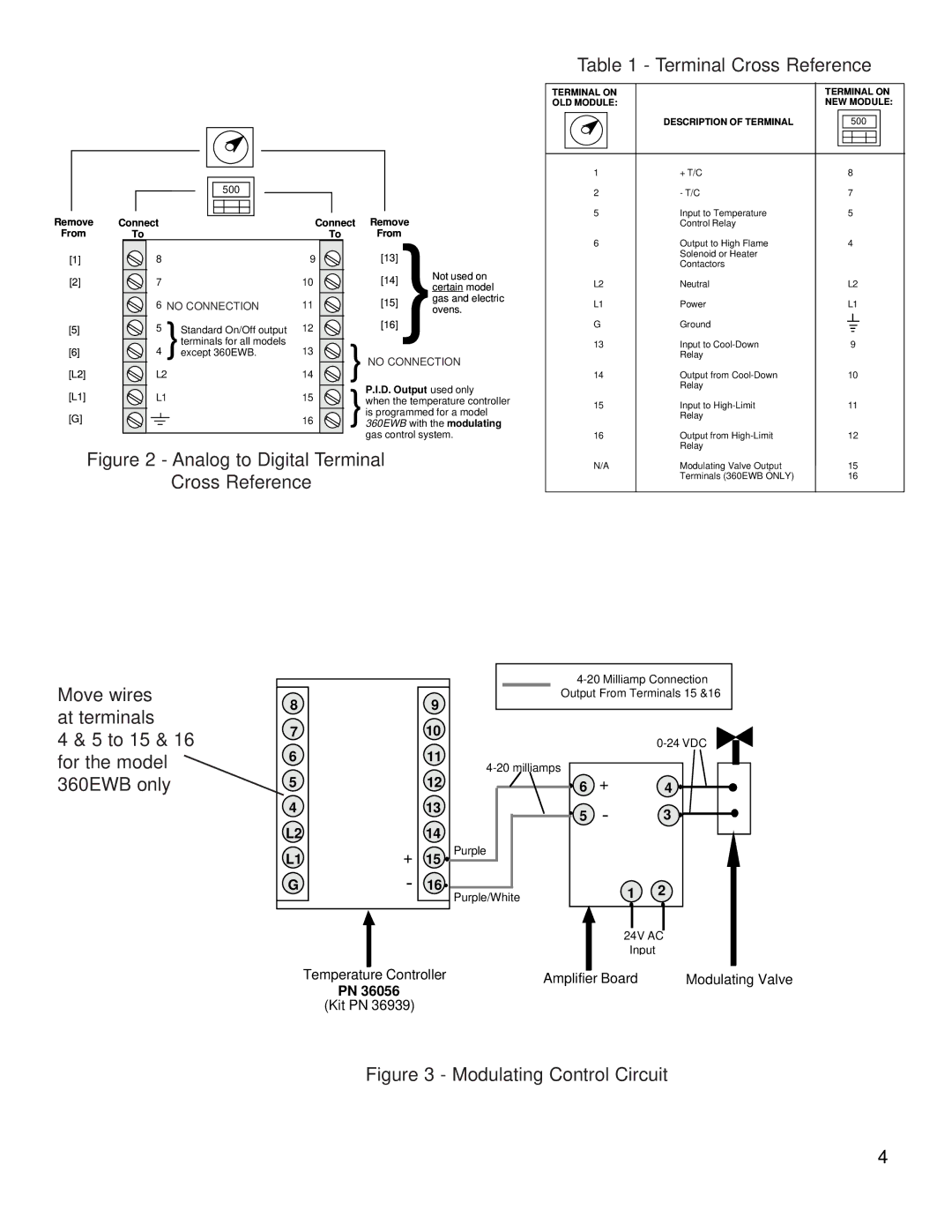
Table 1 - Terminal Cross Reference
|
|
|
|
|
|
|
|
|
|
|
|
|
|
|
|
|
|
|
|
|
|
|
|
|
|
|
|
|
|
|
|
|
|
|
|
|
|
|
|
|
|
|
|
|
|
|
|
|
|
|
|
|
|
|
|
| 500 |
|
|
|
|
|
|
| |||
|
|
|
|
|
|
|
|
|
|
|
|
|
|
|
|
|
Remove | Connect |
|
|
|
|
|
|
|
|
| Connect | Remove | ||||
|
|
|
|
|
|
|
|
| ||||||||
From | To |
|
|
|
|
|
|
|
|
| To | From | ||||
TERMINAL ON |
| TERMINAL ON | ||||||||
OLD MODULE: |
| NEW MODULE: | ||||||||
|
|
|
|
|
|
|
|
|
|
|
|
|
| DESCRIPTION OF TERMINAL |
|
| 500 |
|
| ||
|
|
|
|
|
|
|
|
|
|
|
|
|
|
|
|
|
|
|
|
|
|
|
|
|
|
|
|
|
|
|
|
|
|
|
|
|
|
|
|
|
|
|
|
|
|
|
|
|
|
|
|
|
|
|
|
|
|
|
|
|
|
|
|
|
|
1 |
| + T/C | 8 |
|
|
| ||||
2 |
| - T/C | 7 |
|
|
| ||||
5 |
| Input to Temperature | 5 |
|
|
| ||||
|
|
| Control Relay |
|
|
|
|
|
|
|
6 |
| Output to High Flame | 4 |
|
|
| ||||
[1]
[2]
[5]
[6]
[L2]
[L1]
[G]
8 |
|
|
|
|
| 9 | |||
7 |
|
|
|
|
| 10 | |||
6 |
|
|
|
| 11 | ||||
|
| NO CONNECTION | |||||||
5 |
|
|
|
|
| 12 | |||
|
|
| Standard On/Off output | ||||||
|
|
|
|
|
|
| terminals for all models |
| |
4 |
|
| }except 360EWB. | 13 | |||||
| L2 | 14 | |||||||
| L1 | 15 | |||||||
|
|
|
|
|
|
|
|
| 16 |
|
|
|
|
|
|
|
|
| |
[13]
[14] | Not used on | |
certain model | ||
| ||
| gas and electric | |
[16][15] }ovens. | ||
}NO CONNECTION
P.I.D. Output used only
}when the temperature controller is programmed for a model 360EWB with the modulating gas control system.
| Solenoid or Heater |
|
|
|
|
|
| Contactors |
|
|
|
|
|
L2 | Neutral | L2 | ||||
L1 | Power | L1 | ||||
G | Ground |
|
|
|
|
|
|
|
|
|
| ||
|
|
|
|
| ||
|
|
|
|
|
|
|
13 | Input to | 9 |
|
| ||
| Relay |
|
|
|
|
|
14 | Output from | 10 |
| |||
| Relay |
|
|
|
|
|
15 | Input to | 11 |
| |||
| Relay |
|
|
|
|
|
16 | Output from | 12 |
| |||
| Relay |
|
|
|
|
|
Figure 2 - Analog to Digital Terminal Cross Reference
N/A | Modulating Valve Output | 15 |
| Terminals (360EWB ONLY) | 16 |
Move wires at terminals
4 & 5 to 15 & 16 for the model 360EWB only
8
7
6
5
4
L2
L1
G
+
-
9
10
11
12
13
14
15![]()
16 ![]()
Output From Terminals 15 &16 | ||
|
| |
+ |
| |
6 | 4 | |
5 | - | 3 |
Purple |
|
|
Purple/White |
| 1 2 |
|
| 24V AC |
|
| Input |
Temperature Controller | Amplifier Board | Modulating Valve |
PN 36056
(Kit PN 36939)
Figure 3 - Modulating Control Circuit
4