INSTALLATION INSTRUCTIONS
This manual provides instructions for conversion: |
|
|
|
|
|
|
| |
from |
|
|
|
|
|
| to | |
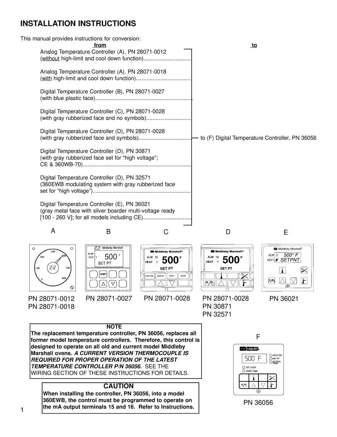
Analog Temperature Controller (A), PN |
|
|
|
|
| |||
|
|
|
|
| ||||
(without |
|
|
|
|
|
| ||
Analog Temperature Controller (A), PN |
|
|
|
| ||||
(with |
|
|
|
|
|
| ||
Digital Temperature Controller (B), PN |
|
|
|
| ||||
(with blue plastic face) |
|
|
|
|
|
|
| |
Digital Temperature Controller (C), PN |
|
|
|
| ||||
(with gray rubberized face and no symbols) |
|
|
|
|
|
| ||
Digital Temperature Controller (D), PN |
|
|
|
| ||||
(with gray rubberized face and symbols) |
|
|
| to (F) Digital Temperature Controller, PN 36056 | ||||
|
|
| ||||||
Digital Temperature Controller (D), PN 30871 |
|
|
|
|
|
|
| |
(with gray rubberized face set for “high voltage”; |
|
|
|
|
|
|
| |
CE & |
|
|
|
|
|
|
| |
Digital Temperature Controller (D), PN 32571 |
|
|
|
|
|
|
| |
(360EWB modulating system with gray rubberized face |
|
|
|
| ||||
set for “high voltage”) |
|
|
|
|
|
|
| |
Digital Temperature Controller (E), PN 36021 |
|
|
|
|
|
|
| |
(gray metal face with silver boarder |
|
|
|
| ||||
[100 - 260 V]; for all models including CE) |
|
|
|
|
|
| ||
A | B |
|
|
|
|
|
|
|
C |
| D |
| E | ||||
| h | h |
|
|
|
|
|
|
|
|
|
|
|
| |
hh | h | h h |
|
| SET PT |
|
|
h | hPN | PN |
|
|
|
| |
PN | PN | PN 36021 | |||||
PN |
|
|
| PN 30871 |
| ||
|
|
|
| PN 32571 |
| ||
NOTE
The replacement temperature controller, PN 36056, replaces all former model temperature controllers. Therefore, this control is designed to operate on all old and current model Middleby Marshall ovens. A CURRENT VERSION THERMOCOUPLE IS REQUIRED FOR PROPER OPERATION OF THE LATEST TEMPERATURE CONTROLLER P/N 36056. SEE THE
WIRING SECTION OF THESE INSTRUCTIONS FOR DETAILS.
CAUTION
When installing the controller, PN 36056, into a model 360EWB, the control must be programmed to operate on
1the mA output terminals 15 and 16. Refer to Instructions.
F |
|
500 F | HEAT ON |
ACTUAL | |
| SET PT |
| TEMP |
SP LOCK |
|
OVER TEMP |
|
PN 36056