h |
| h |
| h | h |
|
| h | h | h |
| h | h |
|
| h | ||||
|
|
|
|
| h |
|
|
|
|
|
| h |
|
hh | h | h |
| h |
|
|
|
|
|
h |
|
|
|
|
|
| |||
|
| hh |
| h |
| h |
|
|
|
|
| h | h | h |
| h |
| ||
|
|
| hh |
| h |
| |||
|
|
| h | h |
|
|
|
| |
|
|
| Purple |
| |||||
| hhh | hh |
| h | h |
| h |
| h |
|
| h | h |
|
|
| |||
|
|
|
|
| Purple/White | ||||
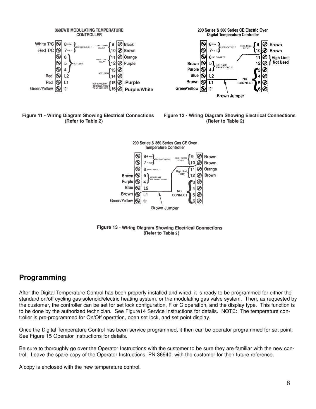
Figure 11 - Wiring Diagram Showing Electrical Connections | Figure 12 - Wiring Diagram Showing Electrical Connections |
(Refer to Table 2) | (Refer to Table 2) |
|
|
|
|
|
|
|
|
| h |
| hh | hh |
| h |
| hh | hh |
| h | |
|
|
|
|
|
|
|
|
| h |
|
|
|
| h |
| h | ||
|
|
|
|
|
|
|
|
| h |
|
| h |
|
|
|
|
|
|
|
|
| h |
|
| h |
|
| h |
|
| h |
|
|
|
| h | |
|
|
| h | h | h |
| h |
|
|
|
|
|
|
| ||||
|
| h |
|
|
| h | h |
|
|
|
| h |
|
|
| |||
|
|
|
|
|
|
| h | h |
|
|
|
|
|
|
| |||
|
|
| h |
|
|
|
|
|
| h |
| h | h | h |
|
|
| |
Figure 13 |
|
|
|
|
|
|
|
|
| hh |
| h |
|
|
| |||
h | h |
|
|
|
|
|
|
|
|
|
|
| h | h | h | hh | ||
Programming
After the Digital Temperature Control has been properly installed and wired, it is ready to be programmed for either the standard on/off cycling gas solenoid/electric heating system, or the modulating gas valve system. Then, as requested by the customer, the controller can be set for set lock configuration, F or C operation, and the display type. This function is to be done by the authorized technician. See Figure14 Service Instructions for details. NOTE: The temperature con- troller is
Once the Digital Temperature Control has been service programmed, it then can be operator programmed for set point. See Figure 15 Operator Instructions for details.
Be sure to thoroughly go over the Operator Instructions with the customer to be sure they are familiar with the new con- trol. Leave the spare copy of the Operator Instructions, PN 36940, with the customer for their future reference.
A copy is enclosed with the new temperature control.
8