manual
installation
owners operating
PS528-Series OVENS Model PS528E
FOR YOUR SAFETY, DO NOT STORE OR USE
MIDDLEBY MARSHALL
MIDDLEBY MARSHALL INC. OVEN LIMITED WARRANTY Non U.S.A
No Quibble Limited Warranty
U.S.A. Only
SERIES PS528 ELECTRICAL SPECIFICATIONS
TABLE OF CONTENTS
TABLE OF CONTENTS
INSTALLATION KIT
SECTION DESCRIPTION
I. MODEL IDENTIFICATION
This Manual Must Be Kept For Future Reference
PS528 SERIES OVEN SPECIFICATIONS
SERIES PS1828 ELECTRICAL SPECIFICATIONS
Main Blower
SECTION DESCRIPTION
Figure 1-4. PS528-Series Oven Components Locations
II. COMPONENT FUNCTION
SECTION DESCRIPTION
Figure 1-6. Cooling Fan
F2. Blank Plates
Figure 1-7. Blank Plates two sizes and an Air Finger
SECTION INSTALLATION
I. UNLOADING
INSTALLATION KIT
PARTS LIST FOR SERIES PS528 ELECTRIC OVEN INSTALLATION KIT
PARTS LIST FOR SERIES PS528 ELECTRIC OVEN
Figure 2-1. PS528-Series Electric Oven Installation Parts
Figure 2-5. MODEL PS528 SINGLE OVEN DIMENSIONS
SECTION INSTALLATION
Figure 2-6. MODEL PS528 DOUBLE OVEN DIMENSIONS
SECTION INSTALLATION
Figure 2-7. MODEL 528 TRIPLE OVEN DIMENSIONS
ELECTRICAL SPECIFICATIONS
UTILITY ROUGH-IN DIMENSIONS AND POSITIONING FOR PS528-SERIES OVENS
Figure 2-9. Typical PS528-Series Ovens Installation
UNIT MUST HAVE AIR VENT PLATES INSTALLED OR WARRANTY WILL BE VOID
Figure 2-10. Typical Electric Oven Data Plate
Services at 847-741-3300. Press 3, then 5 for Technical Support
IV. ELECTRIC SUPPLY FOR ELECTRICALLY HEATED OVENS
Figure 2-11. Junction Connection Box
SECTION INSTALLATION
SECTION OPERATION
I. CONTROL FUNCTIONS
Figure 3-1. PS528-Series Oven Control Functions
C. Heat Switch
A. Door Safety Switch
B. Blower Switch
D. Temperature Controller
chamber - BEGINNING OF TIMING
MEASURING CONVEYOR SPEED
Figure 3-4. Product at entrance end of baking
Figure 3-5. Product at exit end of baking chamber - END OF TIMING
B. Shutdown Procedure
A. Startup Procedures Daily Startup
Power Failure
III. STEP-BY-STEP OPERATION
SECTION OPERATION
Figure 3-6. Control Panel
IV. NORMAL OPERATION - STEP-BY-STEP
A.Daily Startup Procedure
B. daily Shutdown ProcedurE
wait
Display
Temperature Key
Service Key
SP LOCK Light
Oven will not turn on at all appears in display, oven is not heating
V. QUICK REFERENCE TROUBLESHOOTING
light is lit, food product is undercooked
Oven will not heat
SECTION MAINTENANCE
SECTION MAINTENANCE
A. Exterior
I. MAINTENANCE - DAILY
Figure 4-2. Conveyor Belt and Crumb Pan Cleaning
B. Cooling Fan
A. Removing Conveyor From Oven For Cleaning
II. MAINTENANCE - MONTHLY
PRECAUTIONS
Quantity
6. Remove conveyor as shown
B. Air Fingers Disassembly For Cleaning
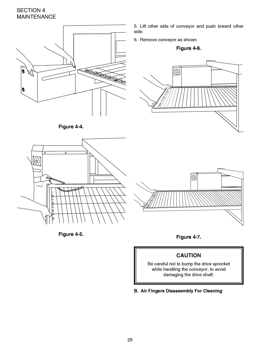
5. Lift other side of conveyor and push toward other side
Be careful not to bump the drive sprocket
T1 T2 T3 B1 B2 B3
Standard Fingers
C. Reassembly of Air Fingers
Figure 4-12. Standard Lower Finger Figure 4-13. Standard Upper Finger
Extended Lip Tab on Outer Plate Flange of Finger Manifold Tab on
Outer Plate
5. Install fingers and blank plates correctly with edges
interlocked and no space between edges
D. Reinstall End Plugs
E. Conveyor Reassembly Into Oven
F. Checking Conveyor Belt Tension
G. Conveyor Belt Link Removal
SECTION 4 MAINTENANCE
H. Attaching Drive Chain
IMPORTANT NOTICES
III. MAINTENANCE - EVERY 3 MONTHS
IV. MAINTENANCE - EVERY 6 MONTHS
A. Electrical Terminals
ENGLISH DESCRIPTION
KEY SPARE PARTS KIT
PS528-SERIES ELECTRIC OVEN KEY SPARE PARTS KIT Figure
QUANTITY
PROBLEM OVEN BLOWER AND CONVEYOR OPERATE YET THE OVEN IS NOT HEATING
SECTION TROUBLESHOOTING
PROBLEM PRODUCTS ARE OVERCOOKED OR UNDERCOOKED
PROBLEM OVEN DOES NOT HEAT
SECTION TROUBLESHOOTING
SECTION 6 - PARTS LIST
ENGLISH
SECTION 6 PARTS LIST
ENGLISH
ENGLISH
SINGLE OVEN EXPLODED VIEW
DESCRIPTION
SECTION 6 PARTS LIST
ENGLISH
ENGLISH
RELAY PANEL
SECTION 6 PARTS LIST
ENGLISH
SECTION PARTS LIST
BLOWER ASSEMBLY
SWITCH, MOMENTARY-12A, NO 2 POLE
ENGLISH
SECTION 6 PARTS LIST
ENGLISH
ENGLISH
CONTROL PANEL
SECTION 6 PARTS LIST
ENGLISH
ENGLISH
SINGLE CONVEYOR
SECTION PARTS LIST
ENGLISH
SECTION ELECTRICAL SCHEMATICS
Wiring Diagram, E208-240V 50/60/1, PS528 P/N 62311 REV B
SECTION ELECTRICAL SCHEMATICS
Wiring Diagram, E208-240V 50/60/3, PS528 P/N 62309 REV B
SECTION ELECTRICAL SCHEMATICS
Wiring Diagram, E380-480V 50/60/3, PS528 P/N 62310 REV B
SECTION ELECTRICAL SCHEMATICS
Wiring Diagram, E380V 50/60/3 CE PS528 P/N 63969 REV B
SECTION ELECTRICAL SCHEMATICS
relieves the manufacturer of all warranty and liability