Manuals
/
Middleby Marshall
/
Kitchen Appliance
/
Oven
Middleby Marshall
PS528 (Triple), PS528E, PS528 (Double)
installation manual
English
Models:
PS528 (Triple)
PS528 (Double)
PS528E
1
44
60
60
Download
60 pages
35.4 Kb
41
42
43
44
45
46
47
48
Troubleshooting
Install
Parts list
Section Electrical Schematics
Maintenance
Symptom
Reassembly of Air Fingers
Shutdown Procedure
Temperature Controller
Page 44
Image 44
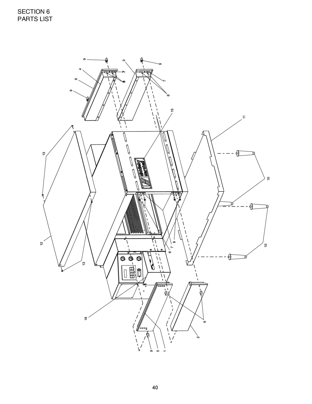
SECTION 6 PARTS LIST
ENGLISH
40
Page 43
Page 45
Page 44
Image 44
Page 43
Page 45
Contents
Owners operating
Page
Middleby Marshall
Table of Contents
Section Description
Model Identification
This Manual Must Be Kept For Future Reference
PS528 Series Oven Specifications
Series PS1828 Electrical Specifications
PS528-Series Oven Components Locations
II. Component Function
Cooling Fan
F2. Blank Plates
Section Installation
Unloading
Parts List for Series PS528 Electric Oven Installation KIT
Single and Double Stack Ovens
Model PS528 Single Oven Dimensions
Model PS528 Double Oven Dimensions
Model 528 Triple Oven Dimensions
II. Ventilation Guidelines
Electric Supply to be Provided by Customer Circuit Breaker
IV. Electric Supply for Electrically Heated Ovens
10. Typical Electric Oven Data Plate
Section Installation
Section Operation
Control Functions
Door Safety Switch
Blower Switch
Heat Switch
Temperature Controller
See Figures 3-4
Measuring Conveyor Speed
Conveyor
Startup Procedures Daily Startup
Power Failure
Shutdown Procedure
III. STEP-BY-STEP Operation
Control Panel
Daily Startup Procedure
IV. Normal Operation STEP-BY-STEP
SP Lock
Quick Reference Troubleshooting
Symptom
Section Maintenance
Maintenance Daily
Exterior
Cooling Fan
Conveyor Belt Figure
Quantity
II. Maintenance Monthly
Removing Conveyor From Oven For Cleaning
Air Fingers Disassembly For Cleaning
T1 T2 T3 B1 B2 B3
Reassembly of Air Fingers
12. Standard Lower Finger
Extended Lip Tab on Outer Plate Flange Finger Manifold
Incorrect Too
Reinstall End Plugs
Conveyor Reassembly Into Oven
Checking Conveyor Belt Tension
Conveyor Belt Link Removal
Attaching Drive Chain
III. Maintenance Every 3 Months
IV. Maintenance Every 6 Months
Important Notices
Electrical Terminals
KEY Spare Parts KIT
PS528-SERIES Electric Oven KEY Spare Parts KIT Figure
Section Troubleshooting
Problem Oven does not Heat
Section Troubleshooting
Parts List
English
Single Oven Exploded View
English
Relay Panel
English
Blower Assembly
English
Control Panel
English
Single Conveyor
Section Parts List
Section Electrical Schematics
Wiring Diagram, E208-240V 50/60/3, PS528 P/N 62309 REV B
Wiring Diagram, E380-480V 50/60/3, PS528 P/N 62310 REV B
Wiring Diagram, E380V 50/60/3 CE PS528 P/N 63969 REV B
Section Electrical Schematics
Top
Page
Image
Contents