SECTION 3
OPERATION
II.COMPONENT INFORMATION AND LOCATION (Figures 3-1 and 3-2)
A. Door Safety Switch
The Door Safety Switch is located at the lower right side of control panel opening. Opening the control panel door permits this switch to open, disconnecting power to all electrical controls.
CAUTION
Do NOT touch the wires going to this safety switch. Current is always present.
B. Blower Switch
The blower switch has two positions. The switch must be “ON” or “I” for the main blowers to come on and permit the oven to run. The fan circulates the air throughout the oven and must stay on during baking and during the cool down cycle above 200°F (93°C) to prevent blower bearing damage. To protect the blower motor and bear- ings a thermostatic override is built into the oven. If the temperature inside the oven is over 180°F (82°C) the
main blower will continue to run after the blower switch is turned to the “OFF” or “O” position.
C. Heat Switch
Turning the HEAT switch to “ON” or “I” will energize the electric heating system. This switch is in series with the blower fan motor and high temperature override switch. Both switches must be closed before the heating elements an be energized.
D. Temperature Controller
The temperature controller is a
The temperature controller contains a
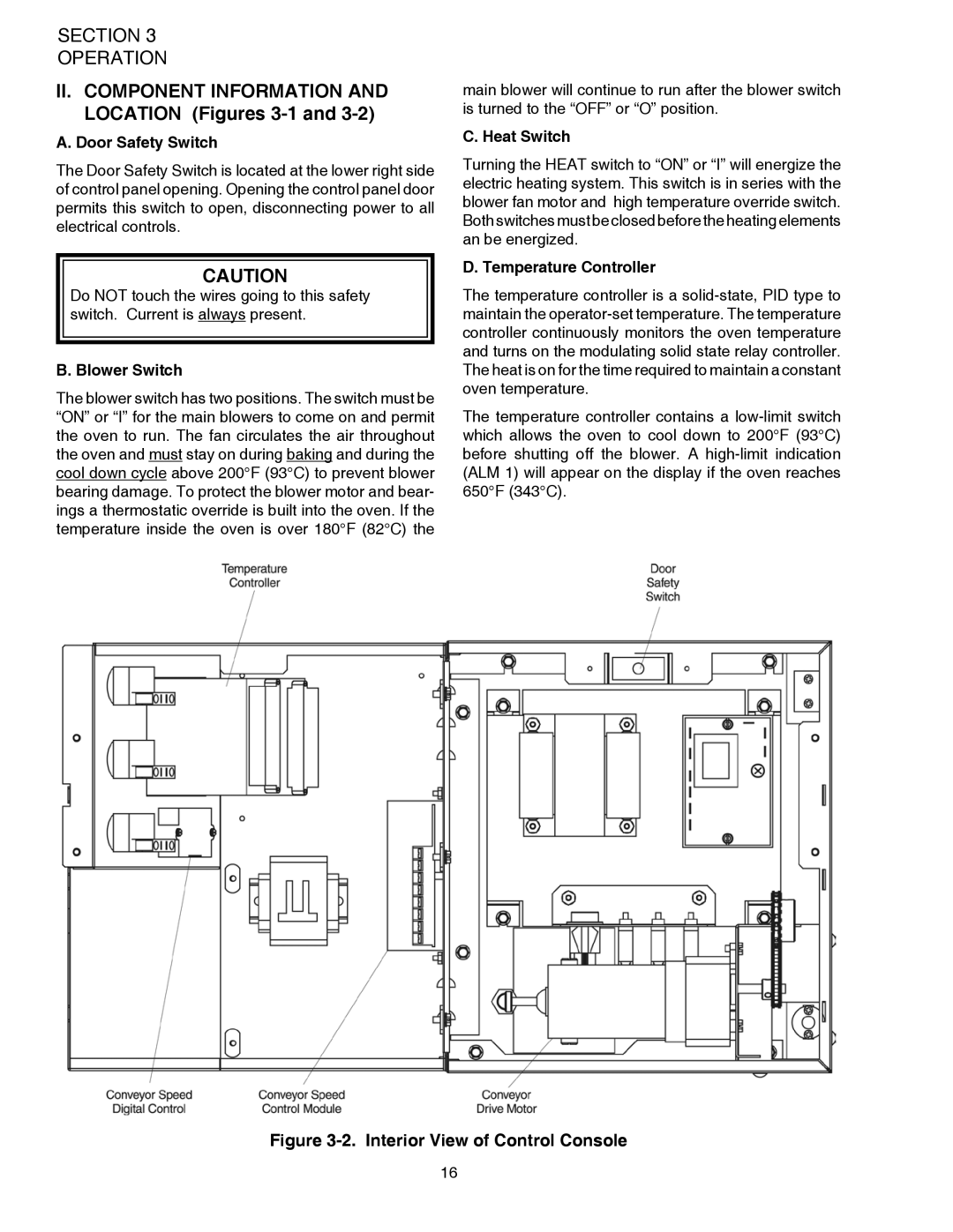
Figure 3-2. Interior View of Control Console
16