Manuals
/
Miller Electric
/
Power Tools
/
Welder
Miller Electric
12VS
manual
Gun Consumables Information
Models:
12VS
1
27
44
44
Download
44 pages
25.7 Kb
24
25
26
27
28
29
30
31
Troubleshooting
Specification
Parts list
Error codes
Equipment Connection Diagram
Symbol Usage
Welding Wire can cause injury
Cleaning Drive Rolls
Safety
Service
Page 27
Image 27
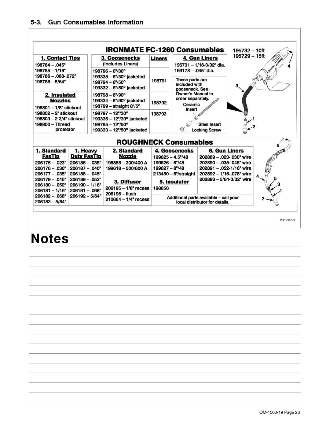
5-3.
Gun Consumables Information
200
007-B
Notes
OM-1500-19
Page 23
Page 26
Page 28
Page 27
Image 27
Page 26
Page 28
Contents
File MIG Gmaw
OM-1500-19 219 185P
Processes
Description
From Miller to You
Table of Contents
Directives
Standards
Decstat1/07
HOT Parts can cause severe burns
Symbol Usage
Arc Welding Hazards
Electric Shock can kill
Flying Metal or Dirt can injure eyes
Fumes and Gases can be hazardous
ARC Rays can burn eyes and skin
Welding can cause fire or explosion
Moving Parts can cause injury
Welding Wire can cause injury
Fire or Explosion hazard
Falling Unit can cause injury
About Implanted Medical Devices
Principal Safety Standards
California Proposition 65 Warnings
EMF Information
UNE Décharge Électrique peut entraîner la mort
Symboles utilisés
DES Pièces Chaudes peuvent provoquer des brûlures graves
LES Fumées ET LES GAZ peuvent être dangereux
LE Soudage peut provoquer un in cendie ou une explosion
LA Chute DE L’APPAREIL peut blesser
LE Bruit peut endommager l’ouïe
LES Bouteilles peuvent exploser si elles sont endommagées
Risque D’INCENDIE OU D’EXPLO- Sion
Proposition californienne 65 Avertissements
LES Fils DE Soudage peuvent provoquer des blessures
LE Soudage À L’ARC risque de provoquer des interférences
Principales normes de sécurité
Information EMF
En ce qui concerne les implants médicaux
OM-1500-19
Disconnect input plug or power before working on machine
− Definitions
Keep your head out of the fumes
Weee Label For Products Sold Within The EU
Manufacturer’s Rating Label For CE Products
Symbols And Definitions
Weight
− Installation
Specifications
Power
Equipment Connection Diagram
Cleaning Drive Rolls
Installing And Aligning Wire Guide And Drive Rolls
Installing Wire Guide And Drive Rolls
Aligning Wire Guide And Drive Rolls
Connecting Shielding Gas
Connecting Welding Gun And Voltage Sensing Clamp
Weld Cable Sizes
Connecting Weld Cable
Threading Welding Wire
Installing And Threading Welding Wire
150 mm Pull and hold wire cut off end Tighten Clockwise
Installing Wire And Adjusting Hub Tension
Display Board PC20 DIP Switch Settings
Controls With Meters
− Operation
Controls Without Meters
Gun Consumables Information
Wire Speed Control Settings
− Maintenance & Troubleshooting
Overload Protection And Thermostat Protection
Thermostat Protection
Troubleshooting
Motor Overload Error
Diagnostics
Error Indications
Communication Error
OM-1500-19
Circuit Diagram For Wire Feeder
− Electrical Diagram
19 20 51 68
− Parts List
Diagram Part Marking Description Quantity
207
Front Panel Assembly without Meters
Front Panel Assembly with Meters
Drive Roll & Wire Guide Kits 2 Drive Roll
Start Your Professional Welding Career Now
SOCKET/WRENCH Selection Table Standard Metric
Material Thickness Gauge
Service
Your distributor also gives
Support
Your distributor and/or equipment manufacturer’s
To locate a Distributor or Service Agency visit
Miller Electric Mfg. Co
For assistance in filing or settling claims, contact
Top
Page
Image
Contents