SECTION 4 – OPERATION
4-1. Front Panel Controls
1 |
| 2 | 3 | 4 | |||||||
|
|
|
|
|
|
|
|
|
|
|
|
|
|
|
|
|
|
|
|
|
|
|
|
|
|
|
|
|
|
|
|
|
|
|
|
|
|
|
|
|
|
|
|
|
|
|
|
|
|
|
|
|
|
|
|
|
|
|
|
|
|
|
|
|
|
|
|
|
|
|
|
|
|
|
|
|
|
|
|
|
|
|
|
|
|
|
|
|
|
|
|
|
|
|
|
|
|
|
|
|
|
|
|
|
|
|
|
|
|
|
|
|
|
|
|
|
|
|
|
7 | 6 | 5 |
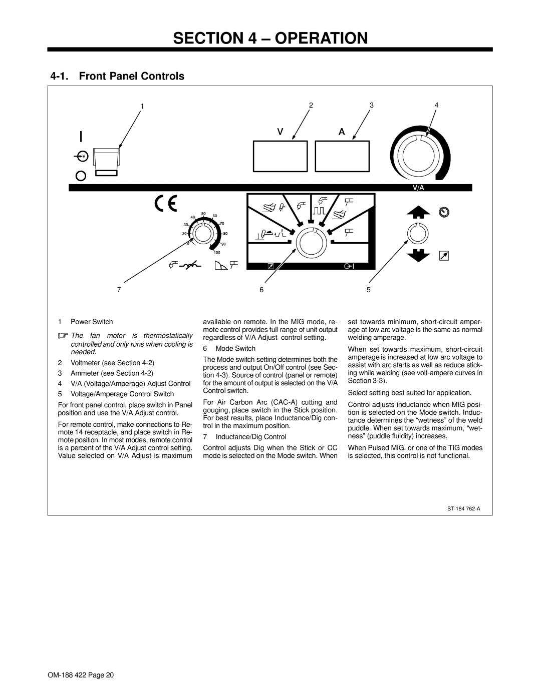
1 Power Switch
.The fan motor is thermostatically controlled and only runs when cooling is needed.
2Voltmeter (see Section
3Ammeter (see Section
4V/A (Voltage/Amperage) Adjust Control
5Voltage/Amperage Control Switch
For front panel control, place switch in Panel position and use the V/A Adjust control.
For remote control, make connections to Re- mote 14 receptacle, and place switch in Re- mote position. In most modes, remote control is a percent of the V/A Adjust control setting. Value selected on V/A Adjust is maximum
available on remote. In the MIG mode, re- mote control provides full range of unit output regardless of V/A Adjust control setting.
6 Mode Switch
The Mode switch setting determines both the process and output On/Off control (see Sec- tion
For Air Carbon Arc
7 Inductance/Dig Control
Control adjusts Dig when the Stick or CC mode is selected on the Mode switch. When
set towards minimum,
When set towards maximum,
Select setting best suited for application.
Control adjusts inductance when MIG posi- tion is selected on the Mode switch. Induc- tance determines the “wetness” of the weld puddle. When set towards maximum, “wet- ness” (puddle fluidity) increases.
When Pulsed MIG, or one of the TIG modes is selected, this control is not functional.