|
| . A complete Parts List is available at www.MillerWelds.com |
| ||
| Socket | Information |
| A | 24 volts ac. Protected by supplementary protector CB2. |
24 VOLTS AC | B | Contact closure to A completes 24 volts ac contactor control circuit. |
| ||
| C | Command reference; 0 to +10 volts dc. |
REMOTE OUTPUT CONTROL | D | Remote control circuit common. |
| E | 0 to +10 volts dc input command signal from remote control. | |
| F | Current feedback; 1 volt per 100 amperes. | |
| H | Voltage feedback; 1 volt per 10 arc volts. | |
| I | 115 volts, 15 amperes, 60 Hz ac. Protected by supplementary protector CB1. | |
115 VOLTS AC | J | Contact closure to I completes 115 volts ac contactor control circuit. | |
| |||
GND | K | Chassis common. | |
G | Circuit common for 24 and 115 volts ac circuits. | ||
| |||
REMOTE POWER ON/OFF | * | To remote On/Off switch. | |
* | |||
|
| ||
REMOTE VOLTAGE SENSING | * | Voltage sensing signal from Negative | |
* | Voltage sensing signal from Positive (+) weld output terminal. | ||
| |||
* Not Used |
|
|
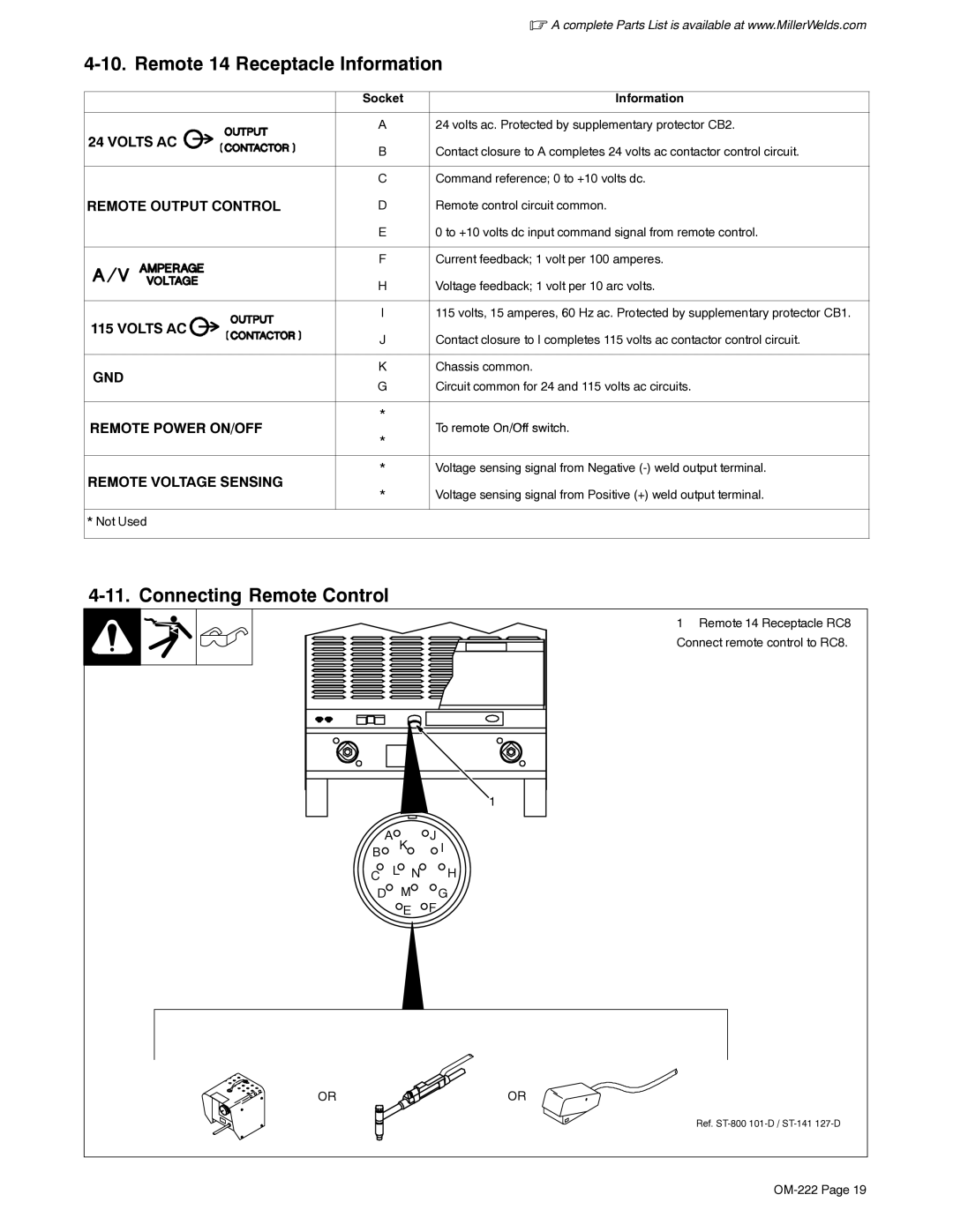
4-11. Connecting Remote Control
1 Remote 14 Receptacle RC8 Connect remote control to RC8.
1
A K | J I | |
B |
|
|
C | L N | H |
D | M | G |
| E | F |
OR | OR |
Ref.