. A complete Parts List is available at www.MillerWelds.com
6-2. Fuse F1
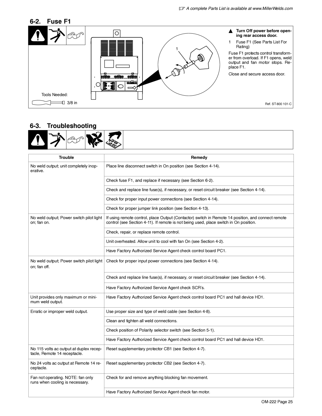
Tools Needed:
3/8 in
YTurn Off power before open- ing rear access door.
| 1 Fuse F1 (See Parts List For |
1 | Rating) |
|
Fuse F1 protects control transform- er from overload. If F1 opens, weld output and fan motor stops. Re- place F1.
Close and secure access door.
Ref.
6-3. Troubleshooting
Trouble | Remedy |
|
|
No weld output; unit completely inop- | Place line disconnect switch in On position (see Section |
erative. |
|
|
|
| Check fuse F1, and replace if necessary (see Section |
|
|
| Check and replace line fuse(s), if necessary, or reset circuit breaker (see Section |
|
|
| Check for proper input power connections (see Section |
|
|
| Check for proper jumper link position (see Section |
|
|
No weld output; Power switch pilot light | If using remote control, place Output (Contactor) switch in Remote 14 position, and connect remote |
on; fan on. | control (see Section |
|
|
| Check, repair, or replace remote control. |
|
|
| Unit overheated. Allow unit to cool with fan On (see Section |
|
|
| Have Factory Authorized Service Agent check control board PC1. |
|
|
No weld output; Power switch pilot light | Check for proper input power connections (see Section |
on; fan off. |
|
|
|
| Check and replace line fuse(s), if necessary, or reset circuit breaker (see Section |
|
|
| Have Factory Authorized Service Agent check SCR’s. |
|
|
Unit provides only maximum or mini- | Have Factory Authorized Service Agent check control board PC1 and hall device HD1. |
mum weld output. |
|
|
|
Erratic or improper weld output. | Use proper size and type of weld cable (see Section |
|
|
| Clean and tighten all weld connections. |
|
|
| Check position of Polarity selector switch (see Section |
|
|
| Have Factory Authorized Service Agent check control board PC1 and hall device HD1. |
|
|
No 115 volts ac output at duplex recep- | Reset supplementary protector CB1 (see Section |
tacle, Remote 14 receptacle. |
|
|
|
No 24 volts ac output at Remote 14 re- | Reset supplementary protector CB2 (see Section |
ceptacle. |
|
|
|
Fan not operating. NOTE: fan only | Check for and remove anything blocking fan movement. |
runs when cooling is necessary. |
|
|
|
| Have Factory Authorized Service Agent check fan motor. |
|
|