4-5. Selecting A Location
Movement
2
OR
1
Tipping
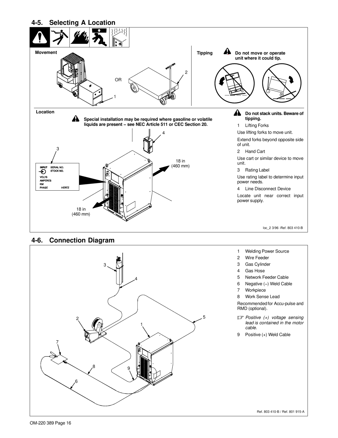
![]() ! Do not move or operate unit where it could tip.
! Do not move or operate unit where it could tip.
Location
![]() ! Special installation may be required where gasoline or volatile liquids are present − see NEC Article 511 or CEC Section 20.
! Special installation may be required where gasoline or volatile liquids are present − see NEC Article 511 or CEC Section 20.
4
3
18 in
![]() (460 mm)
(460 mm)
18 in
(460 mm)
 ! Do not stack units. Beware of tipping.
1 Lifting Forks
Use lifting forks to move unit.
Extend forks beyond opposite side of unit.
2 Hand Cart
Use cart or similar device to move unit.
3 Rating Label
Use rating label to determine input power needs.
4 Line Disconnect Device
Locate unit near correct input power supply.
loc_2 3/96
4-6. Connection Diagram
3
2
7
| 1 | Welding Power Source | |
| 2 | Wire Feeder | |
| 3 | Gas Cylinder | |
| 4 | Gas Hose | |
4 | 5 | Network Feeder Cable | |
6 | Negative (−) Weld Cable | ||
| |||
| 7 | Workpiece | |
| 8 | Work Sense Lead | |
| Recommended for | ||
| RMD (optional). | ||
5. Positive (+) voltage sensing
1 | lead is contained in the motor | |
cable. | ||
| ||
| 9 Positive (+) Weld Cable |
89
6
Ref. 803