Manuals
/
Miller Electric
/
Power Tools
/
Welder
Miller Electric
Axcess 450
manual
220 420-B
Models:
Axcess 450
1
43
52
52
Download
52 pages
28.38 Kb
40
41
42
43
44
45
46
47
Troubleshooting
Specs
Install
Parts list
Connection Diagram
Symbol Usage
Welding Wire can cause injury
Maintenance
Recommended Setup Procedures
Windtunnel Assembly LH And RH
Page 43
Image 43
220
420-B
OM-220
389 Page 37
Page 42
Page 44
Page 43
Image 43
Page 42
Page 44
Contents
File Advanced Manufacturing Systems
OM-220 389J
Processes
Description
From Miller to You
Table of Contents
− Troubleshooting
Standards
Directives
Decstat1/07
Page
HOT Parts can cause severe burns
Symbol Usage
Arc Welding Hazards
Electric Shock can kill
Flying Metal or Dirt can injure eyes
Fumes and Gases can be hazardous
ARC Rays can burn eyes and skin
Welding can cause fire or explosion
Moving Parts can cause injury
Welding Wire can cause injury
Fire or Explosion hazard
Falling Unit can cause injury
About Implanted Medical Devices
Principal Safety Standards
California Proposition 65 Warnings
EMF Information
UNE Décharge Électrique peut entraîner la mort
Symboles utilisés
LES Fumées ET LES GAZ peuvent être dangereux
DES Pièces Chaudes peuvent provoquer des brûlures graves
LE Soudage peut provoquer un in cendie ou une explosion
LA Chute DE L’APPAREIL peut blesser
LE Bruit peut endommager l’ouïe
LES Bouteilles peuvent exploser si elles sont endommagées
Risque D’INCENDIE OU D’EXPLO
LES Fils DE Soudage peuvent provoquer des blessures
Proposition californienne 65 Avertissements
LE Soudage À L’ARC risque de provoquer des interférences
Information EMF
Principales normes de sécurité
En ce qui concerne les implants médicaux
OM-220 389
Keep your head out of the fumes
Disconnect input plug or power before working on machine
− Definitions
Manufacturer’s Warning Label Definitions
Weee Label
Manufacturer’s Rating Label
Symbols And Definitions
I1max
I1eff
17-3/32 in 434 mm 17-3/8 in 441 mm 19-3/32 in 485 mm
− Installation
Specifications
Dimensions And Weight
Overheating
Duty Cycle And Overheating
Volt-Ampere Curves
100% Duty Cycle At 450 Amperes
Selecting a Location
Connection Diagram
Do not stack units. Beware of tipping
Rear Panel Receptacles And Supplementary Protectors
Incorrect Installation
Connecting To Weld Terminals
50/60 Hz
Network Wire Feeder Receptacle Functions
Electrical Service Guide
Pin
Welding Power Source Input Power Connections
Connecting Input Power
Disconnect Device Input Power Connections
Selecting Weld Cable Sizes
− Recommended Setup Procedures
Gun TravelWCL Current Flow Path
Welding Circuit
Best
Using Multiple Welding Power Sources
Wire Feeder Drop in the workpiece. The voltage drop
Bad Setup
Supporting separate voltage feedback to OM-220 389
Better Setup
Best Setup
− Operation
Front Panel Switches
PDA Port PC Port OM-220 389
Routine Maintenance
− Maintenance
Blowing Out Inside of Unit
Exploding Parts can cause injury
− Safety Precautions for Servicing
Shock Hazard from testing
Servicing Hazards
California Proposition 65 Warnings
Removing Cover and Measuring Input Capacitor Voltage
− Troubleshooting
Diagnostic LED’s On Process Control Module PC4
Process Control Module PC4 Diagnostic LED’s
Status Diagnosis
Circuit board is operating normally
Network And Module Status LED’s Network Status LED’s
Module Status LED’s
Red
Trouble Remedy
Troubleshooting
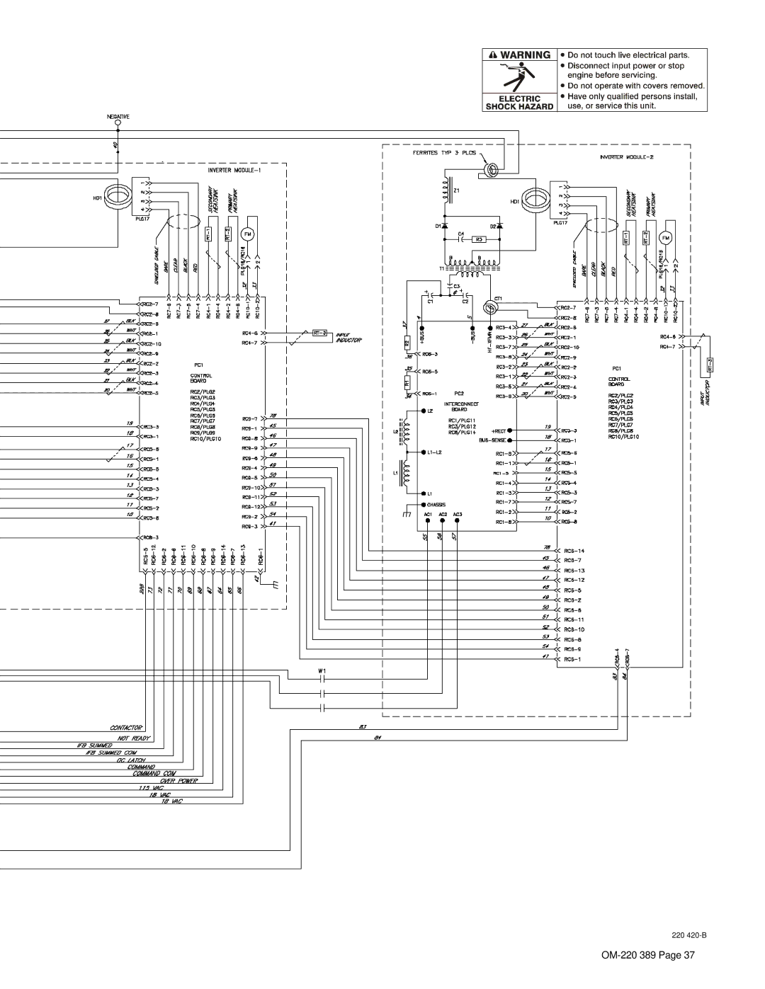
Circuit Diagram For Welding Power Source
− Electrical Diagrams
220 420-B
16 − Fig
− Parts List
Windtunnel Assembly LH And RH
Windtunnel Assembly LH And RH -1Item
Top Tray Assembly
Rear Panel Assembly
Front Panel Assembly
Dia Part
Your distributor also gives
Service
Support
Your distributor and/or equipment manufacturer’s
To locate a Distributor or Service Agency visit
Miller Electric Mfg. Co
For assistance in filing or settling claims, contact
Top
Page
Image
Contents