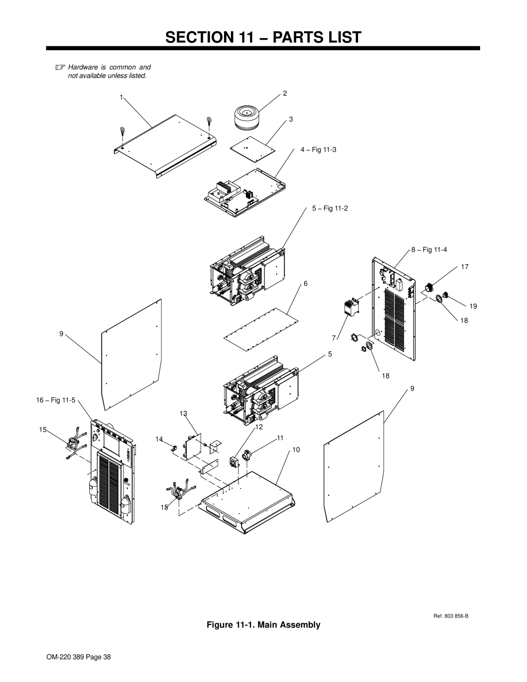
Manuals
/
Brands
/
Power Tools
/
Welder
/
Miller Electric
/
Power Tools
/
Welder
Miller Electric
Axcess 450
SECTION 11 PARTS LIST
1
44
52
52
Download
52 pages, 2.6 Mb
OM-220 389 Page 38
SECTION 1
1 − P
ARTS LIST
.
Hardware
is common and
not available unless listed.
Ref. 803 856-B
2
3
6
7
5
9
11
10
15
14
15
9
1
12
13
4 − Fig 1
1-3
5 − Fig 1
1-2
8 − Fig 1
1-4
16 − Fig 1
1-5
17
19
18
18
Figure 1
1-1. Main Assembly
Contents
Main
Axcess 450
From Miller to You
Page
TABLE OF CONTENTS
Declaration of Conformity for European Community (CE) Products
.
Manufacturer:European Contact:
Page
SECTION 1 SAFETY PRECAUTIONS - READ BEFORE USING
1-1. Symbol Usage
.
1-2. Arc Welding Hazards
ELECTRIC SHOCK can kill.
ARC RAYS can burn eyes and skin.
WELDING can cause fire or explosion.
FLYING M E TAL o r DIRT can injure eyes.
BUILDUP OF GAS can injure or kill.
MAGNETIC FIELDS can affect Implanted Medical Devices.
1-3. Additional Symbols For Installation, Operation, And Maintenance
FIRE OR EXPLOSION hazard.
FALLING UNIT can cause injury.
OVERUSE can cause OVERHEATING
FLYING SPARKS can cause injury.
1-4. California Proposition 65 Warnings
1-5. Principal Safety Standards
1-6. EMF Information
SECTION 2
2-1. Symboles utiliss
.
2-2. Dange rs relatifs au soudage larc
UNE DCHARGE LECTRIQUE peut entraner la mort.
DES PICES CHAUDES peuvent provoquer des brlures graves.
t
tre
LES FUMES ET LES GAZ peuvent
dangereux.
2-3.
e
Risque DINCENDIE OU DEXPLO- SION.
LA CHUTE DE LAPPAREIL peut blesser.
LEMPLOI EXCESSIF peut SUR- CHAUFFER LQUIPEMENT.
2-4. Proposition californienne 65 Avertissements
2-5. Principales normes de scurit
2-6. Information EMF
Page
SECTION 3 DEFINITIONS
3-1. Manufacturers Warning Label Definitions
= <60
3-2. WEEE Label
Page
SECTION 4 INSTALLATION
. 4-1. Specifications
4-2. Dimensions And Weight
4-3. Duty Cycle And Overheating
A/V
4-4. Volt-Ampere Curves
.
CV MODE
4-5. Selecting A Location
!
.
4-6. Connection Diagram
.
4-7. Rear Panel Receptacles And Supplementary Protectors
4-8. Connecting To Weld Terminals
!
.
4-9. Network Wire Feeder Receptacle Functions
4-10. Electrical Service Guide
.
4-11. Connecting Input Power
!
3
SECTION 5 RECOMMENDED SETUP PROCEDURES
5-1. Selecting Weld Cable Sizes*
!
)
*
5-2. Welding Circuit .
Standard Welding Circuit
Large Weld Structure
5-3. Arranging Welding Cables To Reduce Welding Circuit Inductance Bad
Better
Best
.
5-4. Using Multiple Welding Power Sources
5-5. Voltage Sensing Lead And Work Cable Connections For Multiple Welding Arcs
A. Bad Setup
B. Better Setup
C. Best Setup
SECTION 6 OPERATION
6-1. Front Panel Switches
SECTION 7 MAINTENANCE
7-1. Routine Maintenance
!
7-2. Blowing Out Inside of Unit
!
SECTION 8 SAFETY PRECAUTIONS FOR SERVICING
8-1. Symbol Usage
.
8-2. Servicing Hazards
ELECTRIC SHOCK can kill.
8-3. California Proposition 65 Warnings
8-4. EMF Information
SECTION 9 TROUBLESHOOTING
9-1. Removing Cover and Measuring Input Capacitor Voltage
!
9-2. Process Control Module PC4 Diagnostic LEDs
9-3. Diagnostic LEDs On Process Control Module PC4
9-4. Network And Module Status LEDs
9-5. Troubleshooting
Page
Page
SECTION 11 PARTS LIST
Figure 11-1. Main Assembly
Page
Page
Page
Page
Page
Page
Warranty Questions?
Call 1-800-4-A-MILLER for your local Miller distributor.
Effective January 1, 2007 (Equipment with a serial number preface of LH or newer)
Please complete and retain with your personal records.
For Service
Always provide Model Name and Serial/Style Number.
Contact a DISTRIBUTOR or SERVICE AGENCY near you.
Owners Record