3-3. Installing Gas Supply
1
6 | 2 |
3
5
4
Argon Gas
8
IN-GAS-OUT
To Torch
7
Tools Needed:
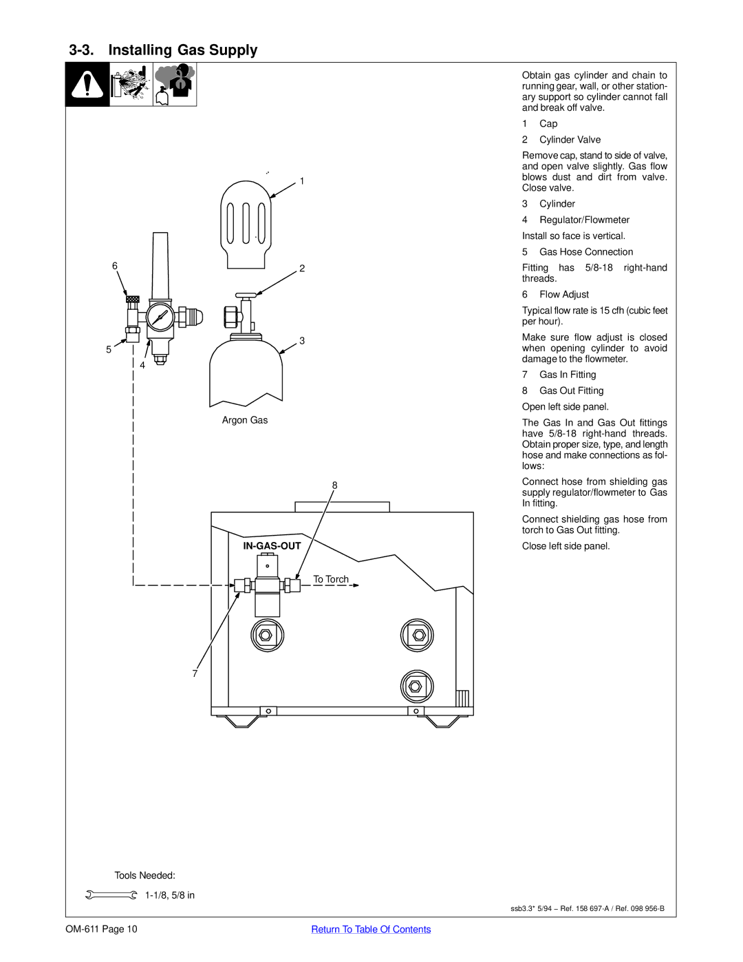
Obtain gas cylinder and chain to running gear, wall, or other station- ary support so cylinder cannot fall and break off valve.
1Cap
2Cylinder Valve
Remove cap, stand to side of valve, and open valve slightly. Gas flow blows dust and dirt from valve. Close valve.
3Cylinder
4Regulator/Flowmeter Install so face is vertical.
5Gas Hose Connection
Fitting has
6 Flow Adjust
Typical flow rate is 15 cfh (cubic feet per hour).
Make sure flow adjust is closed when opening cylinder to avoid damage to the flowmeter.
7Gas In Fitting
8Gas Out Fitting
Open left side panel.
The Gas In and Gas Out fittings have
Connect hose from shielding gas supply regulator/flowmeter to Gas In fitting.
Connect shielding gas hose from torch to Gas Out fitting.
Close left side panel.
ssb3.3* 5/94 − Ref. 158
Return To Table Of Contents |