NOTE
The supplied cord with plugs is for use with CC or CC/CV welding power sources having the proper, matching
3-4. Power Source Plug Information And Connections
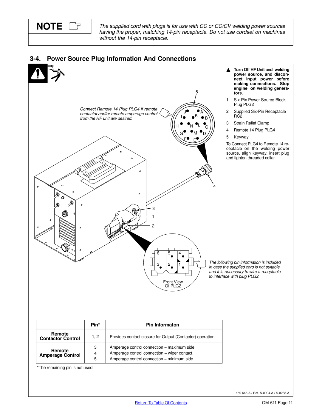
Connect Remote 14 Plug PLG4 if remote contactor and/or remote amperage control from the HF unit are desired.
![]()
![]() 3
3
1
2
5
J![]()
![]() A
A
I ![]()
![]() K
K ![]() B
B
H ![]()
![]() N
N ![]() L C
L C
GM D
F![]() E
E![]()
4
YTurn Off HF Unit and welding power source, and discon- nect input power before making connections. Stop engine on welding genera- tors.
1
2Supplied
3Strain Relief Clamp
4Remote 14 Plug PLG4
5Keyway
To Connect PLG4 to Remote 14 re- ceptacle on the welding power source, align keyway, insert plug and tighten threaded collar.
6 | 5 | 4 |
3 | 2 | 1 |
The following pin information is included in case the supplied cord is not suitable, and it is necessary to wire a receptacle to interface with plug PLG2.
Front View
Of PLG2
| Pin* | Pin Informaton | |
|
|
| |
|
|
| |
Remote | 1, 2 | Provides contact closure for Output (Contactor) operation. | |
Contactor Control | |||
|
| ||
Remote | 3 | Amperage control connection − maximum side. | |
4 | Amperage control connection − wiper contact. | ||
Amperage Control | |||
5 | Amperage control connection − minimum side. | ||
| |||
|
|
|
*The remaining pin is not used.
159
Return To Table Of Contents |