3-7. Connecting To Weld Output Terminals
12
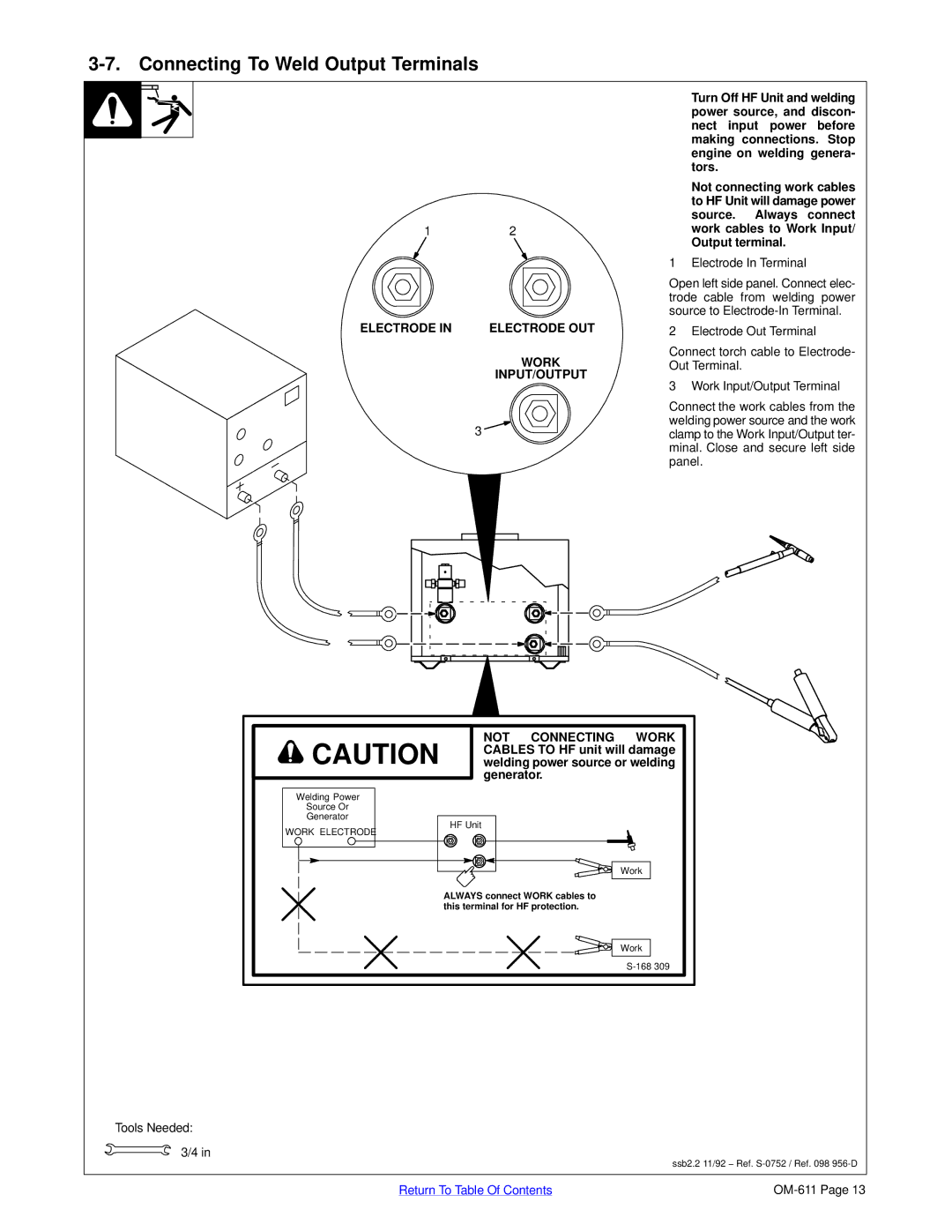
ELECTRODE IN | ELECTRODE OUT |
WORK
INPUT/OUTPUT
3
YTurn Off HF Unit and welding power source, and discon- nect input power before making connections. Stop engine on welding genera- tors.
YNot connecting work cables to HF Unit will damage power source. Always connect work cables to Work Input/ Output terminal.
1 Electrode In Terminal
Open left side panel. Connect elec- trode cable from welding power source to
2 Electrode Out Terminal
Connect torch cable to Electrode- Out Terminal.
3 Work Input/Output Terminal
Connect the work cables from the welding power source and the work clamp to the Work Input/Output ter- minal. Close and secure left side panel.
![]() CAUTION
CAUTION
NOT CONNECTING WORK CABLES TO HF unit will damage welding power source or welding generator.
Welding Power
Source Or
Generator
WORK ELECTRODE
HF Unit
Work
ALWAYS connect WORK cables to this terminal for HF protection.
Work
Tools Needed:
3/4 in
ssb2.2 11/92 − Ref.
Return To Table Of Contents |