3-7. Common Work Connections
1 ![]()
3 ![]()
4
YTurn Off welding power sources by placing Power circuit breakers in the Off position before making any weld output connections.
YDo not connect welding output of dif- ferent polarities to the same struc- ture.
YSee ANSI Z49.1 and OSHA Title 29, Chapter XVII, Part 1910, Subpart Q (addresses at beginning of manual).
YDo not handle or come in contact with two live electrodes at the same time.
YARCING can burn skin or damage electrical equipment. Do not change position of the welding cable connec- tors while welding.
YBe sure the connectors are secure in receptacles before welding.
4
5
YINADEQUATE WORK CABLE CON- NECTIONS can cause serious dam- age to input power service and create a hazardous condition. Connect an electrical cable of adequate size be- tween the isolated terminal and the workpiece whenever the isolated ter- minal is used.
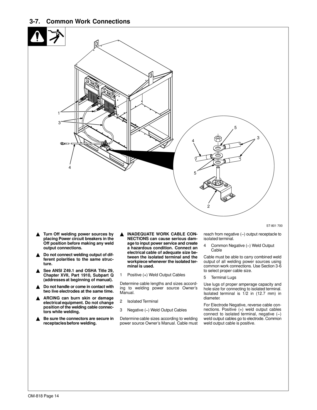
1 Positive (+) Weld Output Cables
Determine cable lengths and sizes accord- ing to welding power source Owner’s Manual.
2Isolated Terminal
3Negative (−) Weld Output Cables
Determine cable sizes according to welding power source Owner’s Manual. Cable must
5
3
2
reach from negative (−) output receptacle to isolated terminal.
4Common Negative (−) Weld Output Cable
Cable must be able to carry combined weld output of all welding power sources using common work connections. Use Section
5 Terminal Lugs
Use lugs of proper amperage capacity and hole size for connecting to isolated terminal. Isolated terminal is 1/2 in (12.7 mm) in diameter.
For Electrode Negative, reverse cable con- nections. Positive (+) weld output cables connect to isolated terminal, negative (−) weld output cables go to electrode. Common weld output cable is positive.