3-9. Connecting Input Power To Rack
2
9
3
4
1 | 6 | 8 | 4 |
5
7 3
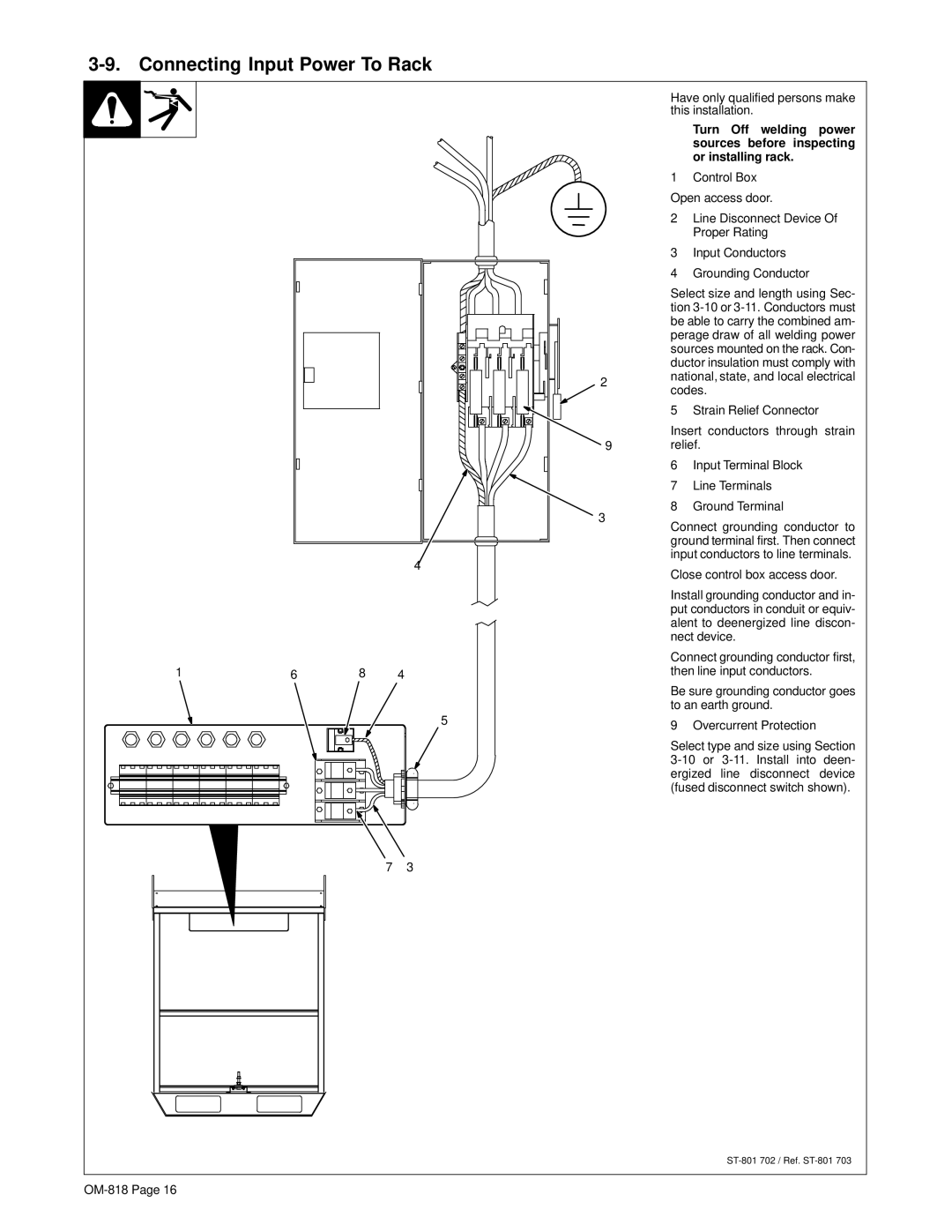
Have only qualified persons make this installation.
YTurn Off welding power sources before inspecting or installing rack.
1Control Box Open access door.
2Line Disconnect Device Of Proper Rating
3Input Conductors
4Grounding Conductor
Select size and length using Sec- tion
5 Strain Relief Connector
Insert conductors through strain relief.
6Input Terminal Block
7Line Terminals
8Ground Terminal
Connect grounding conductor to ground terminal first. Then connect input conductors to line terminals.
Close control box access door.
Install grounding conductor and in- put conductors in conduit or equiv- alent to deenergized line discon- nect device.
Connect grounding conductor first, then line input conductors.
Be sure grounding conductor goes to an earth ground.
9 Overcurrent Protection
Select type and size using Section