3-5. Welding Power Source Input Power Connections
1
1 | 2 | 3 |
6 | 4 | 7 | 5 |
|
|
|
Side View
Tools Needed:
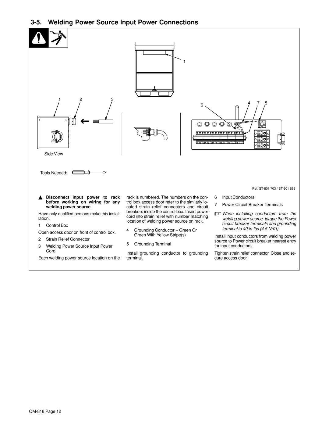
YDisconnect input power to rack before working on wiring for any welding power source.
Have only qualified persons make this instal- lation.
1 Control Box
Open access door on front of control box.
2Strain Relief Connector
3Welding Power Source Input Power Cord
Each welding power source location on the
rack is numbered. The numbers on the con- trol box access door refer to the similarly lo- cated strain relief connectors and circuit breakers inside the control box. Insert power cord into strain relief with number matching location of welding power source on rack.
4Grounding Conductor − Green Or Green With Yellow Stripe(s)
5Grounding Terminal
Install grounding conductor to grounding terminal.
Ref.
6Input Conductors
7Power Circuit Breaker Terminals
.When installing conductors from the welding power source, torque the Power circuit breaker terminals and grounding terminal to 40
Install input conductors from welding power source to Power circuit breaker nearest entry for input conductors.
Tighten strain relief connector. Close and se- cure access door.