Chapter 8 Parallel System
8.3 External Power Distribution
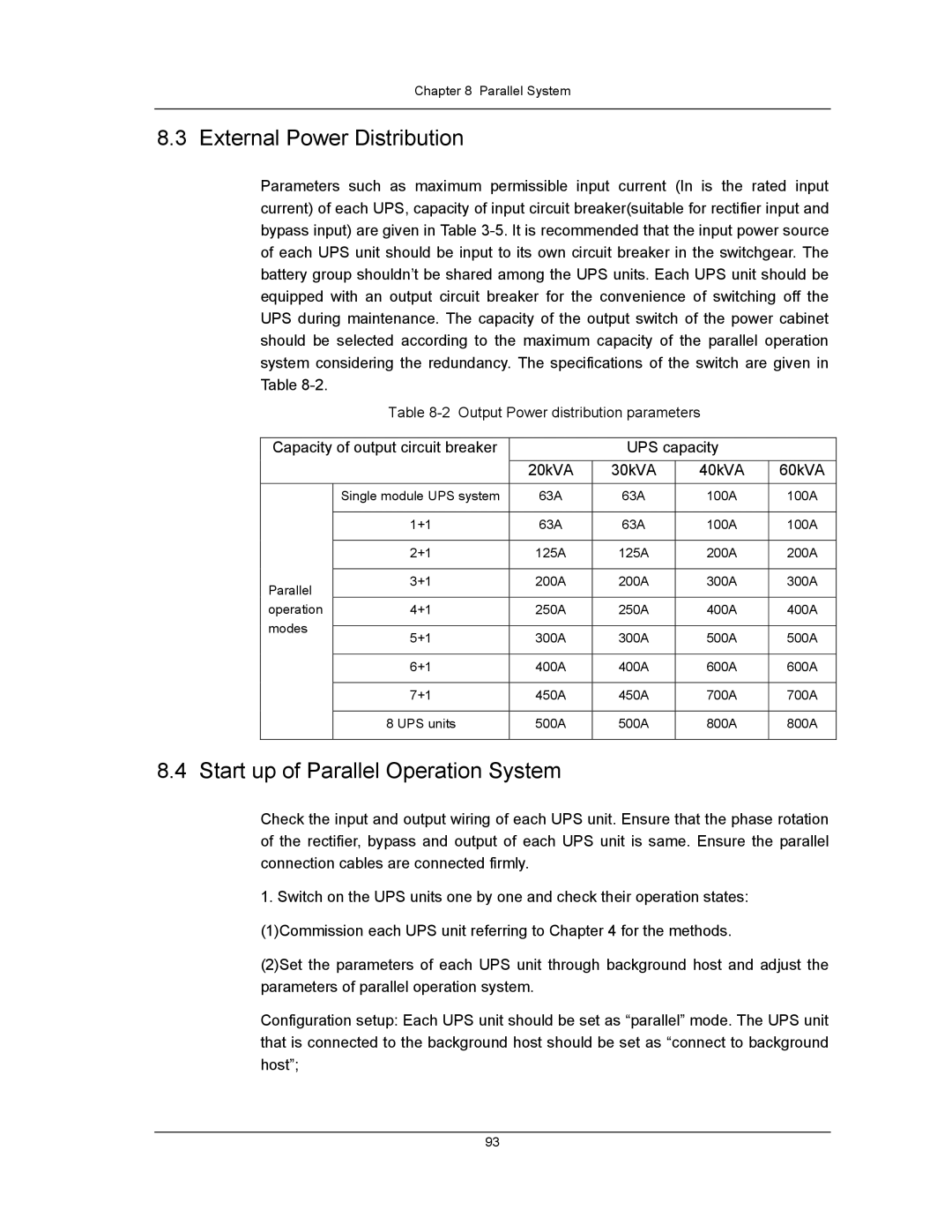
Parameters such as maximum permissible input current (In is the rated input current) of each UPS, capacity of input circuit breaker(suitable for rectifier input and bypass input) are given in Table
Table
Capacity of output circuit breaker |
| UPS capacity |
| |||
|
| 20kVA | 30kVA | 40kVA | 60kVA | |
| Single module UPS system | 63A | 63A | 100A | 100A | |
|
|
|
|
|
| |
| 1+1 | 63A | 63A | 100A | 100A | |
|
|
|
|
|
| |
| 2+1 | 125A | 125A | 200A | 200A | |
|
|
|
|
|
| |
Parallel | 3+1 | 200A | 200A | 300A | 300A | |
|
|
|
|
| ||
operation | 4+1 | 250A | 250A | 400A | 400A | |
modes |
|
|
|
|
| |
5+1 | 300A | 300A | 500A | 500A | ||
| ||||||
|
|
|
|
|
| |
| 6+1 | 400A | 400A | 600A | 600A | |
|
|
|
|
|
| |
| 7+1 | 450A | 450A | 700A | 700A | |
|
|
|
|
|
| |
| 8 UPS units | 500A | 500A | 800A | 800A | |
|
|
|
|
|
| |
8.4 Start up of Parallel Operation System
Check the input and output wiring of each UPS unit. Ensure that the phase rotation of the rectifier, bypass and output of each UPS unit is same. Ensure the parallel connection cables are connected firmly.
1.Switch on the UPS units one by one and check their operation states: (1)Commission each UPS unit referring to Chapter 4 for the methods.
(2)Set the parameters of each UPS unit through background host and adjust the parameters of parallel operation system.
Configuration setup: Each UPS unit should be set as “parallel” mode. The UPS unit that is connected to the background host should be set as “connect to background host”;
93