Chapter 9 Optional Parts
9.7.1 Introduction of SPD24Z
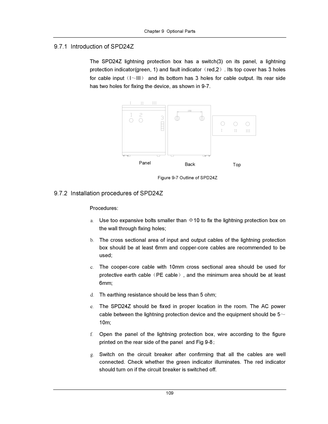
The SPD24Z lightning protection box has a switch(3) on its panel, a lightning protection indicator(green, 1) and fault indicator(red,2). Its top cover has 3 holes for cable input(I~III) and its bottom has 3 holes for cable output. Its rear side has two holes for fixing the device, as shown in
Panel | Back | Top |
Figure 9-7 Outline of SPD24Z
9.7.2 Installation procedures of SPD24Z
Procedures:
a.Use too expansive bolts smaller than Φ10 to fix the lightning protection box on the wall through fixing holes;
b.The cross sectional area of input and output cables of the lightning protection box should be at least 6mm and
c.The
d.Th earthing resistance should be less than 5 ohm;
e.The SPD24Z should be fixed in proper location in the room. The AC power cable between the lightning protection device and the equipment should be 5~ 10m;
f.Open the panel of the lightning protection box, wire according to the figure printed on the rear side of the panel and Fig
g.Switch on the circuit breaker after confirming that all the cables are well connected. Check whether the green indicator illuminates. The red indicator should turn on if the circuit breaker is switched off.
109