Chapter 1 Introduction
1.3 Operation Theory
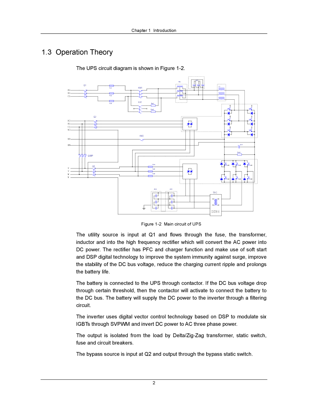
The UPS circuit diagram is shown in Figure
|
|
|
| AC2 |
|
|
|
|
| TR1 |
|
| Q1 | KM1 |
| L1 |
|
A1 | FU1 |
|
|
| |
|
|
|
|
| |
B1 |
|
|
|
|
|
C1 | FU2 |
|
|
|
|
|
|
|
|
| |
| FU3 | KA1 | Res1 |
|
|
|
|
|
| ||
|
|
| Res2 |
|
|
| Q2 |
|
|
|
|
A2 |
|
|
|
|
|
B1 |
|
|
|
|
|
C1 |
|
|
|
|
|
N2 |
|
|
|
|
|
BP |
| KM2 |
|
|
|
|
|
|
|
| |
BN |
|
|
| + | DC1 |
|
|
|
| ||
|
|
|
| Res3 | |
| Q3BP |
|
|
|
|
| Q5 |
| FU4 |
|
|
U |
|
|
|
| |
|
| FU5 |
|
| |
V |
|
|
|
|
|
W |
|
| FU6 |
|
|
|
|
|
|
| |
N |
|
|
|
|
|
|
|
| AC4 | AC3 |
|
|
|
|
| TR2 |
|
|
|
|
| DZN6 |
|
Figure 1-2 Main circuit of UPS
The utility source is input at Q1 and flows through the fuse, the transformer, inductor and into the high frequency rectifier which will convert the AC power into DC power. The rectifier has PFC and charger function and make use of soft start and DSP digital technology to improve the system immunity against surge, improve the stability of the DC bus voltage, reduce the charging current ripple and prolongs the battery life.
The battery is connected to the UPS through contactor. If the DC bus voltage drop through certain threshold, then the contactor will activate to connect the battery to the DC bus. The battery will supply the DC power to the inverter through a filtering circuit.
The inverter uses digital vector control technology based on DSP to modulate six IGBTs through SVPWM and invert DC power to AC three phase power.
The output is isolated from the load by
The bypass source is input at Q2 and output through the bypass static switch.
2