Chapter 1 Introduction
|
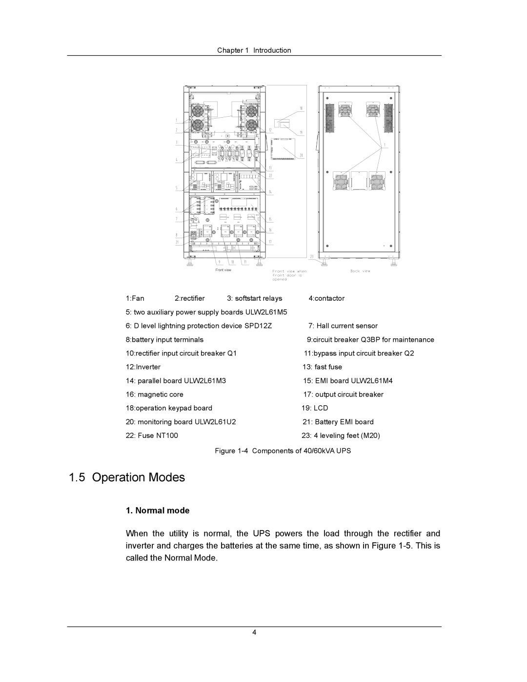
| Front view |
|
1:Fan | 2:rectifier | 3: softstart relays | 4:contactor |
5: two auxiliary power supply boards ULW2L61M5 |
| ||
6: D level lightning protection device SPD12Z | 7: Hall current sensor | ||
8:battery input terminals |
| 9:circuit breaker Q3BP for maintenance | |
10:rectifier input circuit breaker Q1 | 11:bypass input circuit breaker Q2 | ||
12:Inverter |
|
| 13: fast fuse |
14: parallel board ULW2L61M3 | 15: EMI board ULW2L61M4 | ||
16: magnetic core |
| 17: output circuit breaker | |
18:operation keypad board |
| 19: LCD | |
20: monitoring board ULW2L61U2 | 21: Battery EMI board | ||
22: Fuse NT100 |
| 23: 4 leveling feet (M20) | |
|
| Figure | |
1.5 Operation Modes
1. Normal mode
When the utility is normal, the UPS powers the load through the rectifier and inverter and charges the batteries at the same time, as shown in Figure
4