Chapter 3 Electrical Assembly
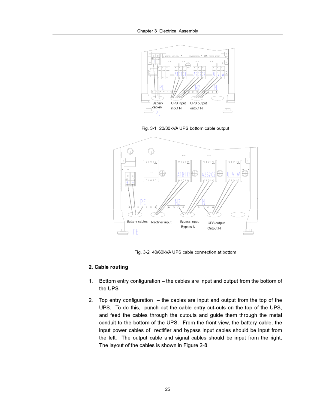
Battery | UPS input | UPS output |
cables | input N | output N |
Fig. 3-1 20/30kVA UPS bottom cable output
Battery cables Rectifier input | Bypass input | UPS output |
| Bypass N | Output N |
|
|
Fig. 3-2 40/60kVA UPS cable connection at bottom
2. Cable routing
1.Bottom entry configuration – the cables are input and output from the bottom of the UPS
2.Top entry configuration – the cables are input and output from the top of the UPS. To do this, punch out the cable entry
25
