The double DSP and MCU form the full digital control system to realize the powerful function of the UPS. The switching between the operation modes is realized by controlling the bypass static switch and the inverter static switch. Advanced battery management prolongs battery life.
Multi-communication ports and management software make it possible for the customer to monitor the UPS performance locally or remotely. The Liebert UPS uses full digital, discrete and on-line parallel operation technology. In parallel operation, several UPS units input parallel logic signals and cross current detection signals through parallel operation boards to enable a maximum of four UPS units to operate in parallel. (N+X) redundancy parallel operation, capacity expansion and hot-standby configuration can be realized. If an additional UPS is required to be added to the system, no auxiliary equipment is required and power to the load need not be interrupted.
1.4 Structure and Layout
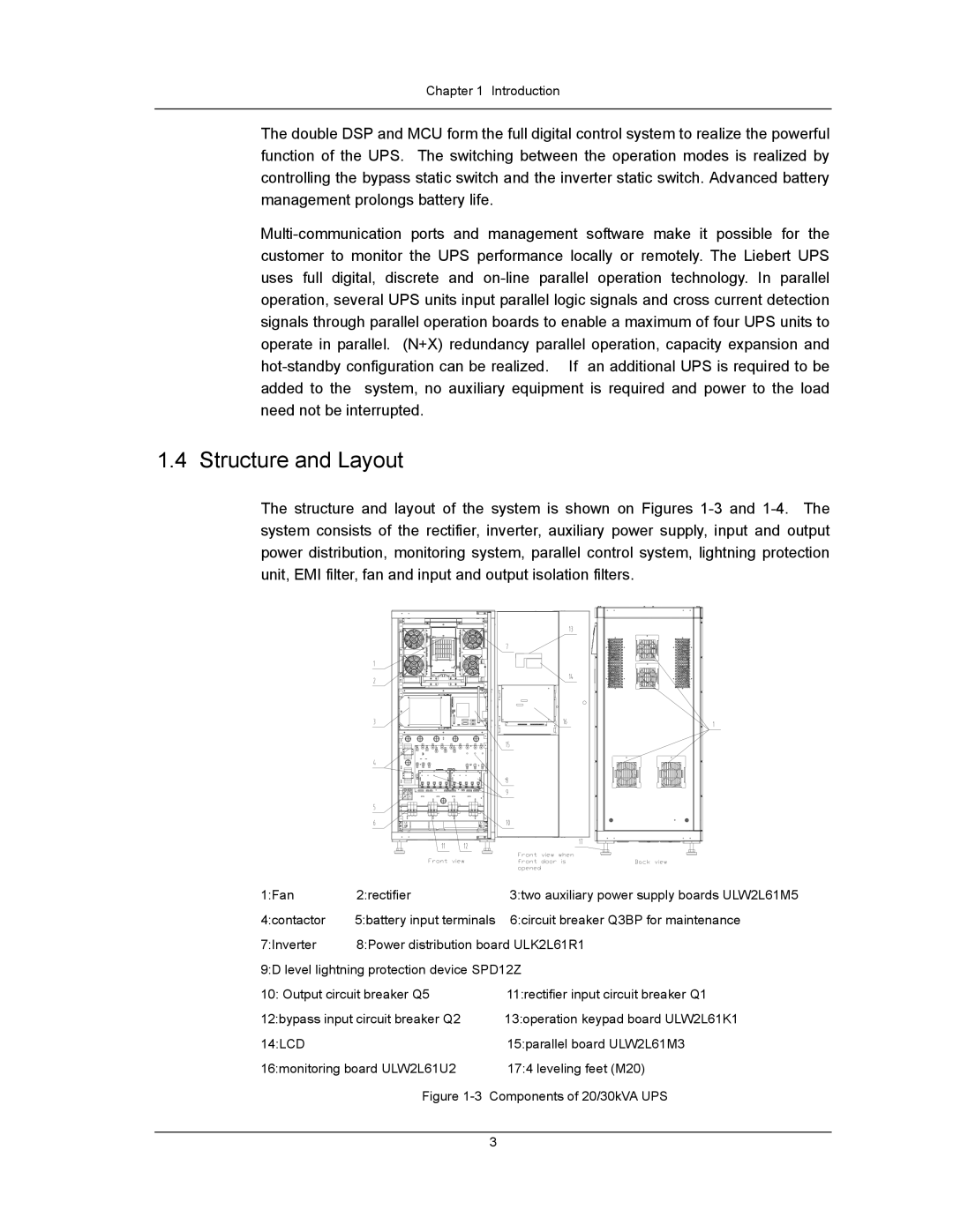
The structure and layout of the system is shown on Figures 1-3 and 1-4. The system consists of the rectifier, inverter, auxiliary power supply, input and output power distribution, monitoring system, parallel control system, lightning protection unit, EMI filter, fan and input and output isolation filters.
1:Fan | 2:rectifier | 3:two auxiliary power supply boards ULW2L61M5 |
4:contactor | 5:battery input terminals | 6:circuit breaker Q3BP for maintenance |
7:Inverter | 8:Power distribution board ULK2L61R1 |
9:D level lightning protection device SPD12Z |
10: Output circuit breaker Q5 | 11:rectifier input circuit breaker Q1 |
12:bypass input circuit breaker Q2 | 13:operation keypad board ULW2L61K1 |
14:LCD | | 15:parallel board ULW2L61M3 |
16:monitoring board ULW2L61U2 | 17:4 leveling feet (M20) |
| Figure 1-3 Components of 20/30kVA UPS |