Chapter 3 Electrical Assembly
Chapter 3 Electrical Assembly
This chapter introduces the connection methods of the power and signal cables.
3.1 Selection of cables
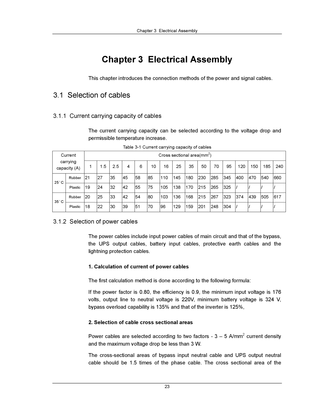
3.1.1 Current carrying capacity of cables
The current carrying capacity can be selected according to the voltage drop and permissible temperature increase.
Table
Current |
|
|
|
|
|
| Cross sectional area(mm2) |
|
|
|
|
| ||||||
carrying |
|
|
|
|
|
|
|
|
|
|
|
|
|
|
|
|
| |
1 | 1.5 | 2.5 | 4 | 6 | 10 |
| 16 | 25 | 35 | 50 | 70 | 95 | 120 | 150 | 185 | 240 | ||
capacity (A) |
| |||||||||||||||||
|
|
|
|
|
|
|
|
|
|
|
|
|
|
|
|
| ||
|
|
|
|
|
|
|
|
|
|
|
|
|
|
|
|
|
|
|
25 C | Rubber | 21 | 27 | 35 | 45 | 58 | 85 |
| 110 | 145 | 180 | 230 | 285 | 345 | 400 | 470 | 540 | 660 |
° |
|
|
|
|
|
|
|
|
|
|
|
|
|
|
|
|
|
|
Plastic | 19 | 24 | 32 | 42 | 55 | 75 |
| 105 | 138 | 170 | 215 | 265 | 325 | / | / | / | / | |
|
| |||||||||||||||||
|
|
|
|
|
|
|
|
|
|
|
|
|
|
|
|
|
|
|
35 C | Rubber | 20 | 25 | 33 | 42 | 54 | 80 |
| 103 | 136 | 168 | 215 | 267 | 323 | 374 | 439 | 505 | 617 |
° |
|
|
|
|
|
|
|
|
|
|
|
|
|
|
|
|
|
|
Plastic | 18 | 22 | 30 | 39 | 51 | 70 |
| 96 | 129 | 159 | 201 | 248 | 304 | / | / | / | / | |
|
| |||||||||||||||||
|
|
|
|
|
|
|
|
|
|
|
|
|
|
|
|
|
|
|
3.1.2 Selection of power cables
The power cables include input power cables of main circuit and that of the bypass, the UPS output cables, battery input cables, protective earth cables and the lightning protection cables.
1. Calculation of current of power cables
The first calculation method is done according to the following formula:
If the power factor is 0.80, the efficiency is 0.9, the minimum input voltage is 176 volts, output line to neutral voltage is 220V, minimum battery voltage is 324 V, bypass overload capability is 135% and that of the inverter is 125%,
2. Selection of cable cross sectional areas
Power cables are selected according to two factors - 3 – 5 A/mm2 current density and the maximum voltage drop be less than 3 W.
The
23