Chapter 9 Optional Parts
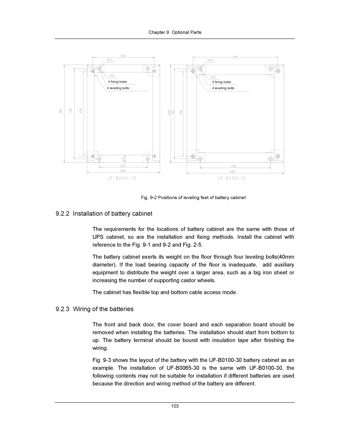
4 fixing holes | 4 fixing holes |
4 levelling bolts | 4 levelling bolts |
Fig. 9-2 Positions of leveling feet of battery cabinet
9.2.2 Installation of battery cabinet
The requirements for the locations of battery cabinet are the same with those of UPS cabinet, so are the installation and fixing methods. Install the cabinet with reference to the Fig.
The battery cabinet exerts its weight on the floor through four leveling bolts(40mm diameter). If the load bearing capacity of the floor is inadequate, add auxiliary equipment to distribute the weight over a larger area, such as a big iron sheet or increasing the number of supporting castor wheels.
The cabinet has flexible top and bottom cable access mode.
9.2.3 Wiring of the batteries
The front and back door, the cover board and each separation board should be removed when installing the batteries. The installation should start from bottom to up. The battery terminal should be bound with insulation tape after finishing the wiring.
Fig. 9-3 shows the layout of the battery with the UF-B0100-30 battery cabinet as an example. The installation of UF-B0065-30 is the same with UF-B0100-30, the following contents may not be suitable for installation if different batteries are used because the direction and wiring method of the battery are different.
103