Chapter 3 Electrical Assemble
3. Cable connection
Note
All the switches should be switched off during cable connection.
1. Feed cables
Feed cables according to the cable entry mode, with reference to Figures
2. Assembling cable lugs to cables
First strip the insulation layer 20 mm from the end. Then insert the conductor into the cable lug. Then press the cable lug against the cable till tight.
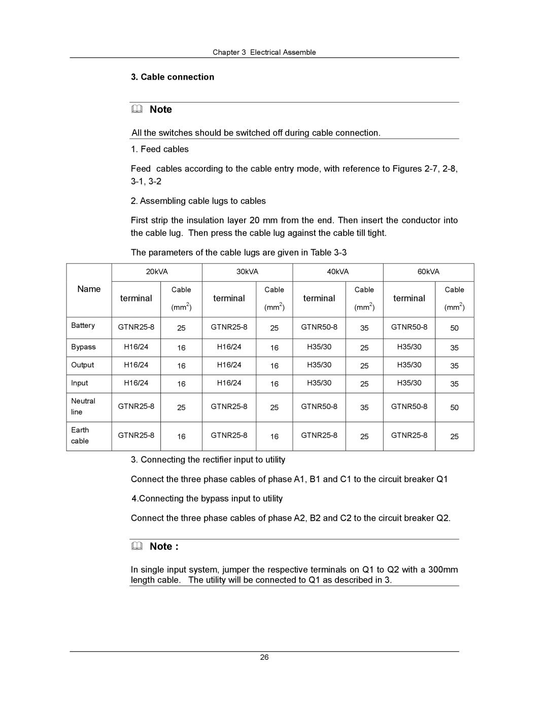
The parameters of the cable lugs are given in Table
| 20kVA |
| 30kVA |
| 40kVA |
| 60kVA |
| ||||
Name |
|
|
|
|
|
|
|
|
|
|
|
|
terminal |
| Cable | terminal |
| Cable | terminal |
| Cable | terminal |
| Cable | |
|
| (mm2) |
| (mm2) |
| (mm2) |
| (mm2) | ||||
|
|
|
|
|
|
|
|
| ||||
|
|
|
|
|
|
|
|
|
|
|
|
|
Battery |
| 25 |
| 25 |
| 35 |
| 50 | ||||
|
|
|
|
|
|
|
|
|
|
|
|
|
Bypass | H16/24 |
| 16 | H16/24 |
| 16 | H35/30 |
| 25 | H35/30 |
| 35 |
|
|
|
|
|
|
|
|
|
|
|
|
|
Output | H16/24 |
| 16 | H16/24 |
| 16 | H35/30 |
| 25 | H35/30 |
| 35 |
|
|
|
|
|
|
|
|
|
|
|
|
|
Input | H16/24 |
| 16 | H16/24 |
| 16 | H35/30 |
| 25 | H35/30 |
| 35 |
|
|
|
|
|
|
|
|
|
|
|
|
|
Neutral |
| 25 |
| 25 |
| 35 |
| 50 | ||||
line |
|
|
|
| ||||||||
|
|
|
|
|
|
|
|
|
|
|
| |
|
|
|
|
|
|
|
|
|
|
|
|
|
Earth |
| 16 |
| 16 |
| 25 |
| 25 | ||||
cable |
|
|
|
| ||||||||
|
|
|
|
|
|
|
|
|
|
|
| |
|
|
|
|
|
|
|
|
|
|
|
|
|
3. Connecting the rectifier input to utility
Connect the three phase cables of phase A1, B1 and C1 to the circuit breaker Q1
4.Connecting the bypass input to utility
Connect the three phase cables of phase A2, B2 and C2 to the circuit breaker Q2.
Note :
In single input system, jumper the respective terminals on Q1 to Q2 with a 300mm length cable. The utility will be connected to Q1 as described in 3.
26