Chapter 3 Electrical Assemble
3)Connection of SNMP Card
Installation of SNMP card
Unpack the SNMP card and place it in the iron case shown in Figure
Connect the cables
On the monitoring board, there is a jack J22 with a cable to plug in directly to the SNMP card, after the SNMP Card is installed. Please do not remove this cable even if the SNMP card is not used.
4)Connection of RS485
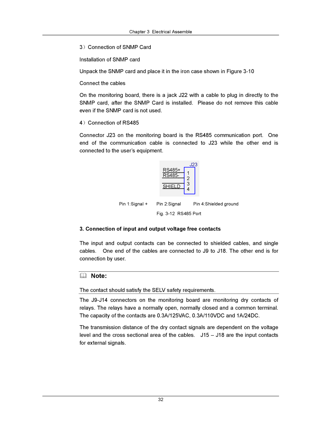
Connector J23 on the monitoring board is the RS485 communication port. One end of the communication cable is connected to J23 while the other end is connected to the user’s equipment.
RS485+
RS485-
SHIELD
Pin 1:Signal + | Pin 2:Signal |
J23
1
2
3
4
Pin 4:Shielded ground
Fig. 3-12 RS485 Port
3. Connection of input and output voltage free contacts
The input and output contacts can be connected to shielded cables, and single cables. One end of the cables are connected to J9 to J18. The other end is for connection by user.
Note:
The contact should satisfy the SELV safety requirements.
The
The transmission distance of the dry contact signals are dependent on the voltage level and the cross sectional area of the cables. J15 – J18 are the input contacts for external signals.
32