Item | Dia. |
| Part | Description | Quantity |
No. | Mkgs. | No. | |||
|
|
|
| Figure |
|
|
|
|
|
|
|
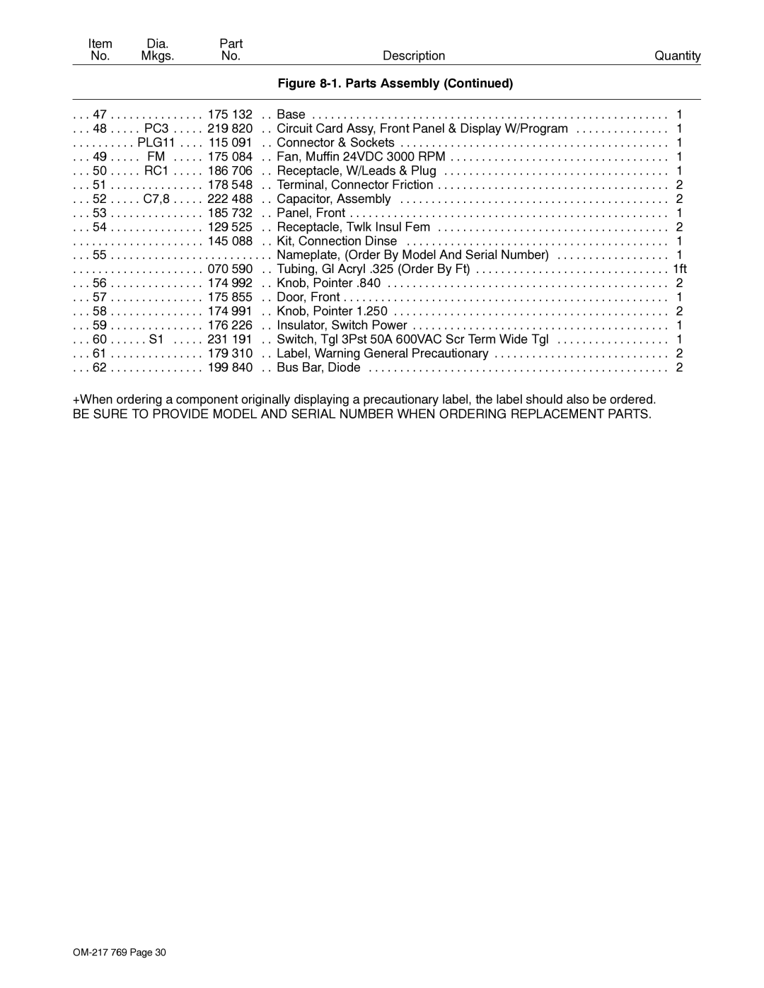
. . . 47 . . . . | . . . . . . | . . . . . | 175 132 | . . Base | . . . 1 |
. . . 48 . . . . | . PC3 | . . . . . | 219 820 | . . Circuit Card Assy, Front Panel & Display W/Program | . . . 1 |
. . . . . . . . . . | PLG11 . . . . | 115 091 | . . Connector & Sockets | . . . 1 | |
. . . 49 . . . . | . FM | . . . . . 175 084 | . . Fan, Muffin 24VDC 3000 RPM | . . . 1 | |
. . . 50 . . . . | . RC1 | . . . . . | 186 706 | . . Receptacle, W/Leads & Plug | . . . 1 |
. . . 51 . . . . | . . . . . . | . . . . . | 178 548 | . . Terminal, Connector Friction | . . . 2 |
. . . 52 . . . . | . C7,8 | . . . . . | 222 488 | . . Capacitor, Assembly | . . . 2 |
. . . 53 . . . . | . . . . . . | . . . . . | 185 732 | . . Panel, Front | . . . 1 |
. . . 54 . . . . | . . . . . . | . . . . . | 129 525 | . . Receptacle, Twlk Insul Fem | . . . 2 |
. . . . . . . . . . | . . . . . . | . . . . . | 145 088 | . . Kit, Connection Dinse | . . . 1 |
. . . 55 . . . . | . . . . . . | . . . . . | . . . . . . . . . | . . Nameplate, (Order By Model And Serial Number) | . . . 1 |
. . . . . . . . . . | . . . . . . | . . . . . | 070 590 | . . Tubing, Gl Acryl .325 (Order By Ft) | . . . 1ft |
. . . 56 . . . . | . . . . . . | . . . . . | 174 992 | . . Knob, Pointer .840 | . . . 2 |
. . . 57 . . . . | . . . . . . | . . . . . | 175 855 | . . Door, Front | . . . 1 |
. . . 58 . . . . | . . . . . . | . . . . . | 174 991 | . . Knob, Pointer 1.250 | . . . 2 |
. . . 59 . . . . | . . . . . . | . . . . . | 176 226 | . . Insulator, Switch Power | . . . 1 |
. . . 60 . . . . | . . S1 | . . . . . 231 191 | . . Switch, Tgl 3Pst 50A 600VAC Scr Term Wide Tgl | . . . 1 | |
. . . 61 . . . . | . . . . . . | . . . . . | 179 310 | . . Label, Warning General Precautionary | . . . 2 |
. . . 62 . . . . | . . . . . . | . . . . . | 199 840 | . . Bus Bar, Diode | . . . 2 |
+When ordering a component originally displaying a precautionary label, the label should also be ordered.
BE SURE TO PROVIDE MODEL AND SERIAL NUMBER WHEN ORDERING REPLACEMENT PARTS.
