6-3. Voltmeter/Ammeter Help Displays
V A
1
![]() HE.L P−0
HE.L P−0
V A
2
![]() HE.L P−1
HE.L P−1
V A
3
![]() HE.L P−2
HE.L P−2
V A
4
![]() HE.L P−3
HE.L P−3
V A
5
![]() HE.L P−4
HE.L P−4
V A
6
![]() HE.L P−5
HE.L P−5
V A
7
![]() HE.L P−6
HE.L P−6
V A
8
![]() HE.L P−7
HE.L P−7
V A
9
![]() HE.L P−8
HE.L P−8
V A
10
![]() HE.L P−9
HE.L P−9
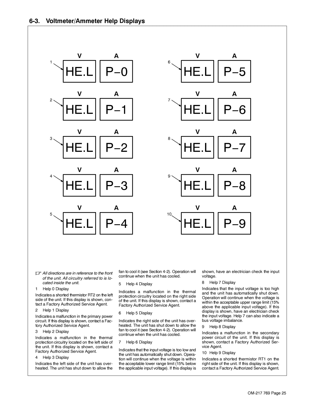
.All directions are in reference to the front
of the unit. All circuitry referred to is lo- cated inside the unit.
1 Help 0 Display
Indicates a shorted thermistor RT2 on the left side of the unit. If this display is shown, con- tact a Factory Authorized Service Agent.
2 Help 1 Display
Indicates a malfunction in the primary power circuit. If this display is shown, contact a Fac- tory Authorized Service Agent.
3 Help 2 Display
Indicates a malfunction in the thermal protection circuitry located on the left side of the unit. If this display is shown, contact a Factory Authorized Service Agent.
4 Help 3 Display
Indicates the left side of the unit has over- heated. The unit has shut down to allow the
fan to cool it (see Section
5 Help 4 Display
Indicates a malfunction in the thermal protection circuitry located on the right side of the unit. If this display is shown, contact a Factory Authorized Service Agent.
6 Help 5 Display
Indicates the right side of the unit has over- heated. The unit has shut down to allow the fan to cool it (see Section
7 Help 6 Display
Indicates that the input voltage is too low and the unit has automatically shut down. Opera- tion will continue when the voltage is within the acceptable lower range limit (15% below the applicable input voltage). If this display is
shown, have an electrician check the input voltage.
8 Help 7 Display
Indicates that the input voltage is too high and the unit has automatically shut down. Operation will continue when the voltage is within the acceptable upper range limit (15% above the applicable input voltage). If this display is shown, have an electrician check the input voltage. Help 7 can also indicate a bus voltage imbalance.
9 Help 8 Display
Indicates a malfunction in the secondary power circuit of the unit. If this display is shown, contact a Factory Authorized Ser- vice Agent.
10 Help 9 Display
Indicates a shorted thermistor RT1 on the right side of the unit. If this display is shown, contact a Factory Authorized Service Agent.