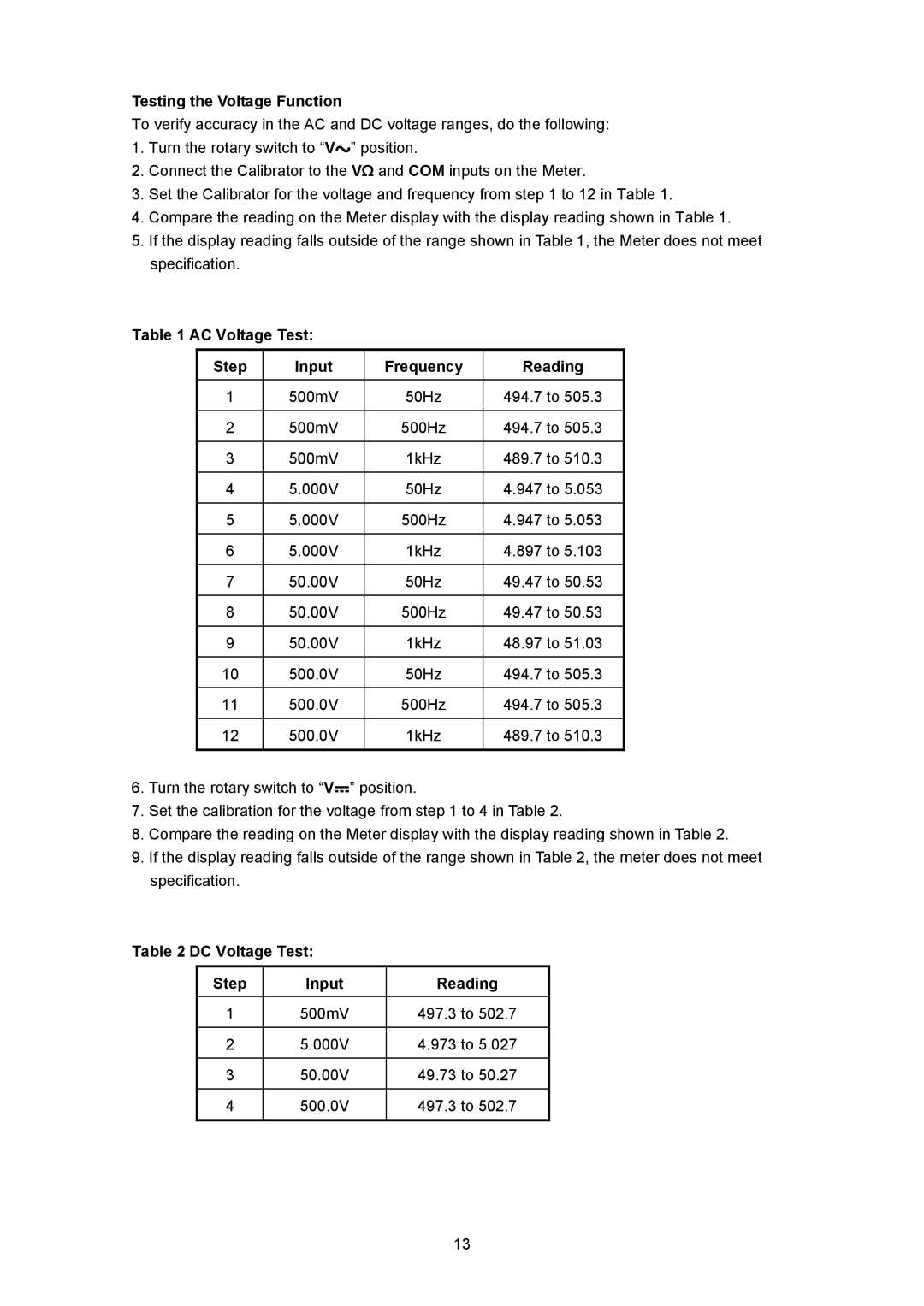
Testing the Voltage Function
To verify accuracy in the AC and DC voltage ranges, do the following:
1.Turn the rotary switch to “V![]() ” position.
” position.
2.Connect the Calibrator to the VΩ and COM inputs on the Meter.
3.Set the Calibrator for the voltage and frequency from step 1 to 12 in Table 1.
4.Compare the reading on the Meter display with the display reading shown in Table 1.
5.If the display reading falls outside of the range shown in Table 1, the Meter does not meet specification.
Table 1 AC Voltage Test:
Step | Input | Frequency | Reading |
1 | 500mV | 50Hz | 494.7 to 505.3 |
|
|
|
|
2 | 500mV | 500Hz | 494.7 to 505.3 |
|
|
|
|
3 | 500mV | 1kHz | 489.7 to 510.3 |
|
|
|
|
4 | 5.000V | 50Hz | 4.947 to 5.053 |
|
|
|
|
5 | 5.000V | 500Hz | 4.947 to 5.053 |
|
|
|
|
6 | 5.000V | 1kHz | 4.897 to 5.103 |
|
|
|
|
7 | 50.00V | 50Hz | 49.47 to 50.53 |
|
|
|
|
8 | 50.00V | 500Hz | 49.47 to 50.53 |
|
|
|
|
9 | 50.00V | 1kHz | 48.97 to 51.03 |
|
|
|
|
10 | 500.0V | 50Hz | 494.7 to 505.3 |
|
|
|
|
11 | 500.0V | 500Hz | 494.7 to 505.3 |
|
|
|
|
12 | 500.0V | 1kHz | 489.7 to 510.3 |
|
|
|
|
6.Turn the rotary switch to “V![]() ” position.
” position.
7.Set the calibration for the voltage from step 1 to 4 in Table 2.
8.Compare the reading on the Meter display with the display reading shown in Table 2.
9.If the display reading falls outside of the range shown in Table 2, the meter does not meet specification.
Table 2 DC Voltage Test:
Step | Input | Reading |
1 | 500mV | 497.3 to 502.7 |
|
|
|
2 | 5.000V | 4.973 to 5.027 |
|
|
|
3 | 50.00V | 49.73 to 50.27 |
|
|
|
4 | 500.0V | 497.3 to 502.7 |
|
|
|
13