Testing the Ampere Function
To verify the accuracy of AC current measurement functions, do the following:
1.Connect the Calibrator to the A and COM inputs on the Meter.
2.Turn the rotary switch to A~.
3.Apply the inputs for steps
4.For each input, compare the readings on the Meter display to the reading in Table 5.
5.If the display reading falls outside of the range shown in the Table 5, the meter does not meet specification.
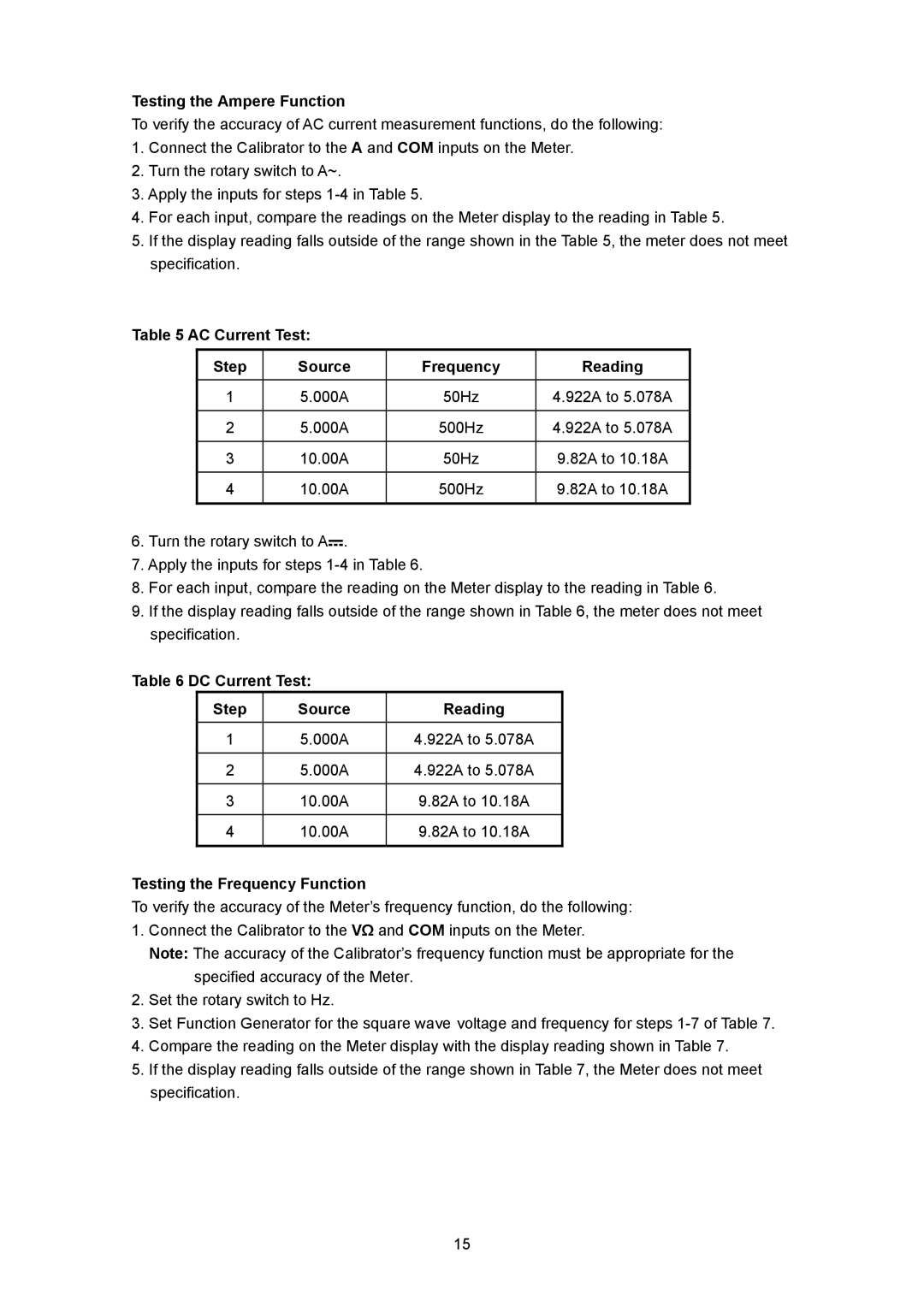
Table 5 AC Current Test:
Step | Source | Frequency | Reading |
1 | 5.000A | 50Hz | 4.922A to 5.078A |
|
|
|
|
2 | 5.000A | 500Hz | 4.922A to 5.078A |
|
|
|
|
3 | 10.00A | 50Hz | 9.82A to 10.18A |
|
|
|
|
4 | 10.00A | 500Hz | 9.82A to 10.18A |
|
|
|
|
6.Turn the rotary switch to A![]() .
.
7.Apply the inputs for steps
8.For each input, compare the reading on the Meter display to the reading in Table 6.
9.If the display reading falls outside of the range shown in Table 6, the meter does not meet specification.
Table 6 DC Current Test:
Step | Source | Reading |
1 | 5.000A | 4.922A to 5.078A |
|
|
|
2 | 5.000A | 4.922A to 5.078A |
|
|
|
3 | 10.00A | 9.82A to 10.18A |
|
|
|
4 | 10.00A | 9.82A to 10.18A |
|
|
|
Testing the Frequency Function
To verify the accuracy of the Meter’s frequency function, do the following:
1.Connect the Calibrator to the VΩ and COM inputs on the Meter.
Note: The accuracy of the Calibrator’s frequency function must be appropriate for the specified accuracy of the Meter.
2.Set the rotary switch to Hz.
3.Set Function Generator for the square wave voltage and frequency for steps
4.Compare the reading on the Meter display with the display reading shown in Table 7.
5.If the display reading falls outside of the range shown in Table 7, the Meter does not meet specification.
15