| Error mode display | Cause | Check procedure and action to take |
|
| ||||||
|
|
|
|
|
|
|
|
|
|
|
|
|
|
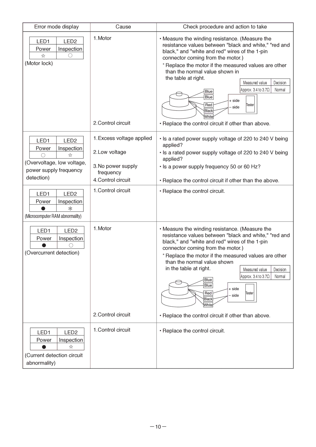
| 1.Motor | • Measure the winding resistance. (Measure the |
|
| |||||
| LED1 | LED2 |
|
| |||||||
|
| resistance values between "black and white," "red and | |||||||||
| Power | Inspection |
| ||||||||
|
| black," and "white and red" wires of the |
|
| |||||||
| ✩ | ● |
|
|
| ||||||
|
| connector coming from the motor.) |
|
| |||||||
(Motor lock) |
|
|
|
| |||||||
|
| * Replace the motor if the measured values are other | |||||||||
|
|
|
| ||||||||
|
|
|
| than the normal value shown in |
|
| |||||
|
|
|
| the table at right. |
|
|
|
| |||
|
|
|
| Measured value |
| Decision |
| ||||
|
|
|
|
|
|
|
|
|
| ||
|
|
|
|
|
|
|
| Approx. 3.4 to 3.7Ω |
| Normal |
|
|
|
|
|
| |||||||
|
|
|
|
|
|
|
|
|
|
|
|
|
|
|
|
|
|
|
|
|
|
|
|
|
|
|
|
|
|
|
|
|
|
|
|
|
|
|
|
| 2.Control circuit | • Replace the control circuit if other than above. |
|
| |||||
|
|
|
|
|
|
|
|
|
|
|
|
| |
|
|
|
|
| 1.Excess voltage applied | • Is a rated power supply voltage of 220 to 240 V being | |||||||
| LED1 | LED2 |
|
| |||||||||
|
|
|
| applied? |
|
|
|
| |||||
| Power | Inspection |
|
| 2.Low voltage |
|
|
|
| ||||
|
|
| • Is a rated power supply voltage of 220 to 240 V being | ||||||||||
| ● | ✩ |
|
| |||||||||
|
|
|
| applied? |
|
|
|
| |||||
(Overvoltage, low voltage, | 3.No power supply |
|
|
|
| ||||||||
• Is a power supply frequency 50 or 60 Hz? |
|
| |||||||||||
power supply frequency |
|
| |||||||||||
frequency |
|
|
|
|
|
|
|
| |||||
detection) |
|
|
|
|
|
|
|
|
|
|
| ||
|
|
| 4.Control circuit | • Replace the control circuit if other than the above. | |||||||||
|
|
|
|
| |||||||||
|
|
|
|
|
|
|
|
|
|
|
|
|
|
|
|
|
|
| 1.Control circuit | • Replace the control circuit. |
|
|
|
| |||
| LED1 | LED2 |
|
|
|
|
|
| |||||
|
|
|
|
|
|
|
|
|
|
| |||
| Power | Inspection |
|
|
|
|
|
|
|
|
|
| |
| ● | ✻ |
|
|
|
|
|
|
|
|
|
| |
(Microcomputer RAM abnormality) |
|
|
|
|
|
|
|
|
| ||||
|
|
|
|
|
|
|
|
|
|
|
|
|
|
|
|
|
|
| 1.Motor | • Measure the winding resistance. (Measure the |
|
| |||||
| LED1 | LED2 |
|
|
| ||||||||
|
|
| resistance values between "black and white," "red and | ||||||||||
| Power | Inspection |
|
| |||||||||
|
|
| black," and "white and red" wires of the |
|
| ||||||||
| ● | ● |
|
|
|
| |||||||
|
|
| connector coming from the motor.) |
|
| ||||||||
(Overcurrent detection) |
|
|
| ||||||||||
| * Replace the motor if the measured values are other | ||||||||||||
|
|
|
|
|
| ||||||||
|
|
|
|
|
| than the normal value shown |
|
|
|
| |||
|
|
|
|
|
| in the table at right. | Measured value |
| Decision |
| |||
|
|
|
|
|
|
|
|
|
| Approx. 3.4 to 3.7Ω |
| Normal |
|
|
|
|
|
|
|
|
|
|
|
|
|
|
|
|
|
|
|
|
|
|
|
|
|
|
|
|
|
|
|
|
|
|
|
|
|
|
|
|
|
|
|
|
|
| 2.Control circuit | • Replace the control circuit if other than above. |
|
|
|
|
|
|
|
| 1.Control circuit | • Replace the control circuit. |
| LED1 | LED2 | ||
|
|
| ||
| Power | Inspection |
|
|
| ● | ✩ |
|
|
(Current detection circuit |
|
| ||
abnormality) |
|
|
| |