(5) Blower
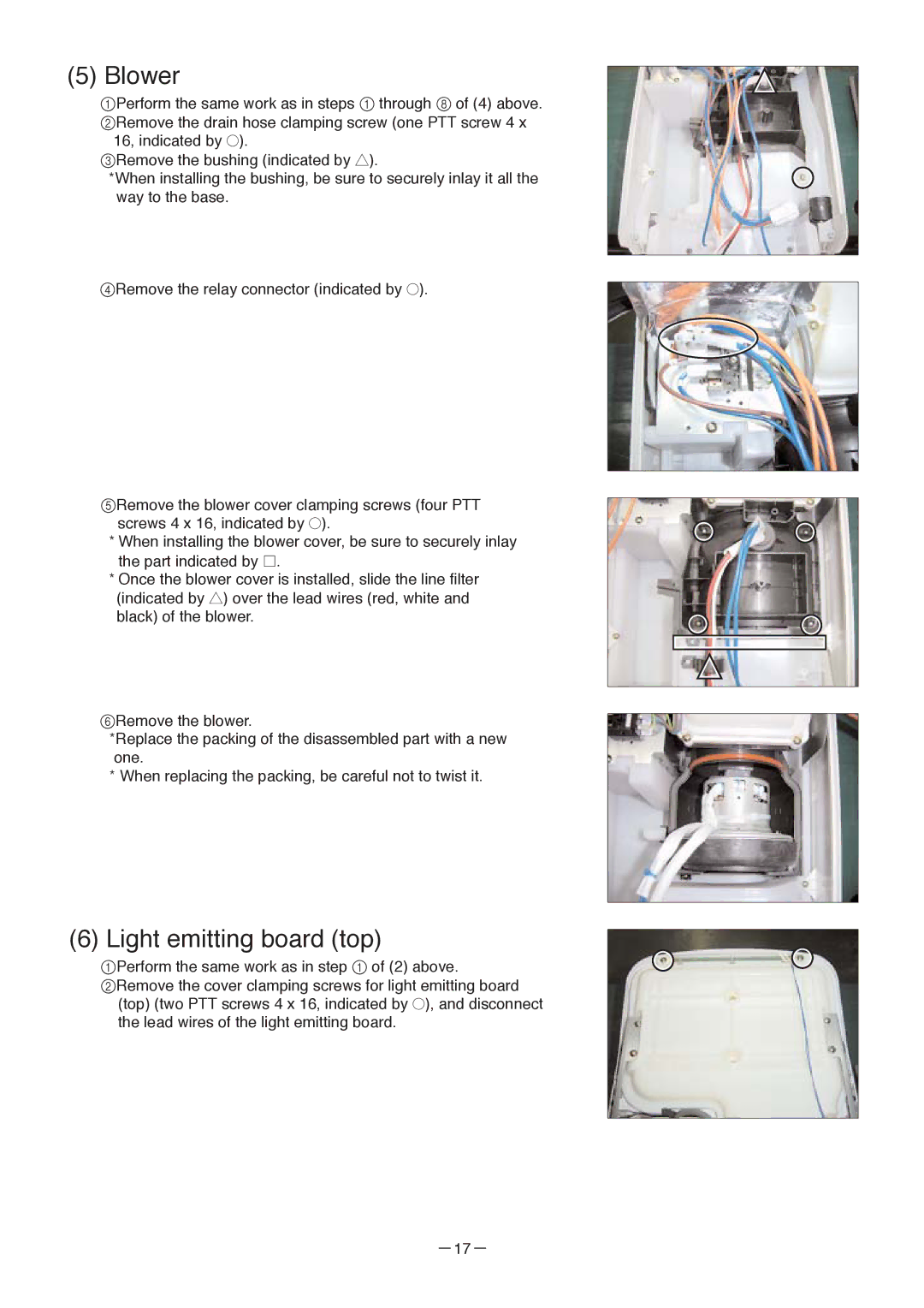
1Perform the same work as in steps 1 through 8 of (4) above. 2Remove the drain hose clamping screw (one PTT screw 4 x
16, indicated by ●).
3Remove the bushing (indicated by ▲).
*When installing the bushing, be sure to securely inlay it all the way to the base.
4Remove the relay connector (indicated by ●).
5Remove the blower cover clamping screws (four PTT screws 4 x 16, indicated by ●).
*When installing the blower cover, be sure to securely inlay the part indicated by ![]() .
.
*Once the blower cover is installed, slide the line filter (indicated by ▲) over the lead wires (red, white and black) of the blower.
6Remove the blower.
*Replace the packing of the disassembled part with a new one.
*When replacing the packing, be careful not to twist it.
(6)Light emitting board (top)
1Perform the same work as in step 1 of (2) above.
2Remove the cover clamping screws for light emitting board (top) (two PTT screws 4 x 16, indicated by ●), and disconnect the lead wires of the light emitting board.