(7) Light emitting board (bottom)
1Perform the same work as in steps 1 through 6 of (5) above. 2Perform the same work as in steps 1 and 2 of (6) above.
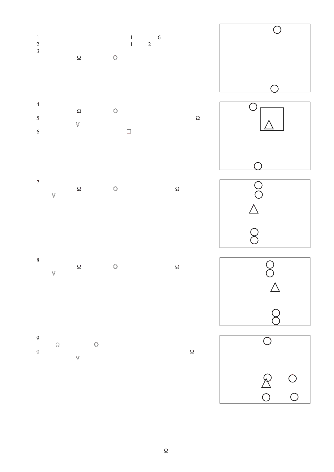
3Remove the right side panel clamping screws (two PTT screws 4 x 16, indicated by ●).
4Remove the left side panel clamping screws (two PTT screws 4 x 16, indicated by ●).
5Remove the reactor clamping screw (one PTT screw 4 x16, indicated by ▲).
6Remove the reactor (indicated by ![]()
![]() ).
).
7Remove the left reinforcing plate clamping screws (four PTT screws 4 x 16, indicated by ●; one PPT screw 4 x 16, indicated by ▲).
8Remove the right reinforcing plate clamping screws (four PTT screws 4 x 16, indicated by ●; one PPT screw 4 x 16, indicated by ▲).
9Remove the panel (front) clamping screws (five PTT screws 4 x 16, indicated by ●).
0Remove the cord clamping screw (one PTT screw 4 x 16, indicated by ▲).