(4) Control board
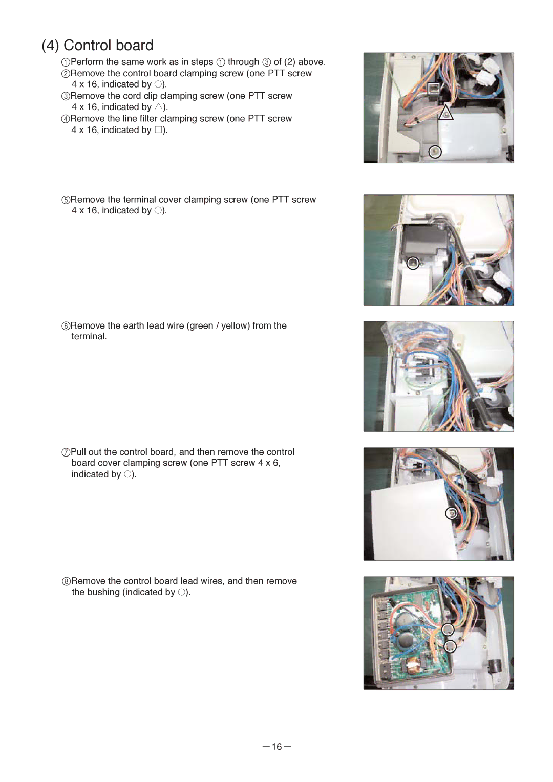
1Perform the same work as in steps 1 through 3 of (2) above. 2Remove the control board clamping screw (one PTT screw
4 x 16, indicated by ●).
3Remove the cord clip clamping screw (one PTT screw 4 x 16, indicated by ▲).
4Remove the line filter clamping screw (one PTT screw 4 x 16, indicated by ![]() ).
).
5Remove the terminal cover clamping screw (one PTT screw 4 x 16, indicated by ●).
6Remove the earth lead wire (green / yellow) from the terminal.
7Pull out the control board, and then remove the control board cover clamping screw (one PTT screw 4 x 6, indicated by ●).
8Remove the control board lead wires, and then remove the bushing (indicated by ●).