6. Troubleshooting
Precautions when diagnosing malfunctions:
●When servicing, be sure to recreate the malfunction 2 to 3 times before initiating repairs.
●When servicing, always keep proper footing.
●When servicing, make sure that the cord is pulled out of the outlet, or the breaker is off if no mains connector is built in the product, so as no electrical shock or injury to occur. Pay sufficient attention when working on the product.
●Always connect the power wire properly.
●When removing the circuit board, always hold it at both ends and remove carefully so as not to apply force to the surface mounted parts.
●When removing the circuit board, be careful of the metal edges on the board.
●When inserting or extracting pin connectors on the circuit board, hold the entire housing. Do not pull on the lead wires.
●If a malfunction of the printed circuit board is suspected, check for any broken
●Be sure to restore same settings as those on the one just replaced.
*The names of the parts indicated are compatible with those listed under the "Name of part" in the chapter "Parts list".
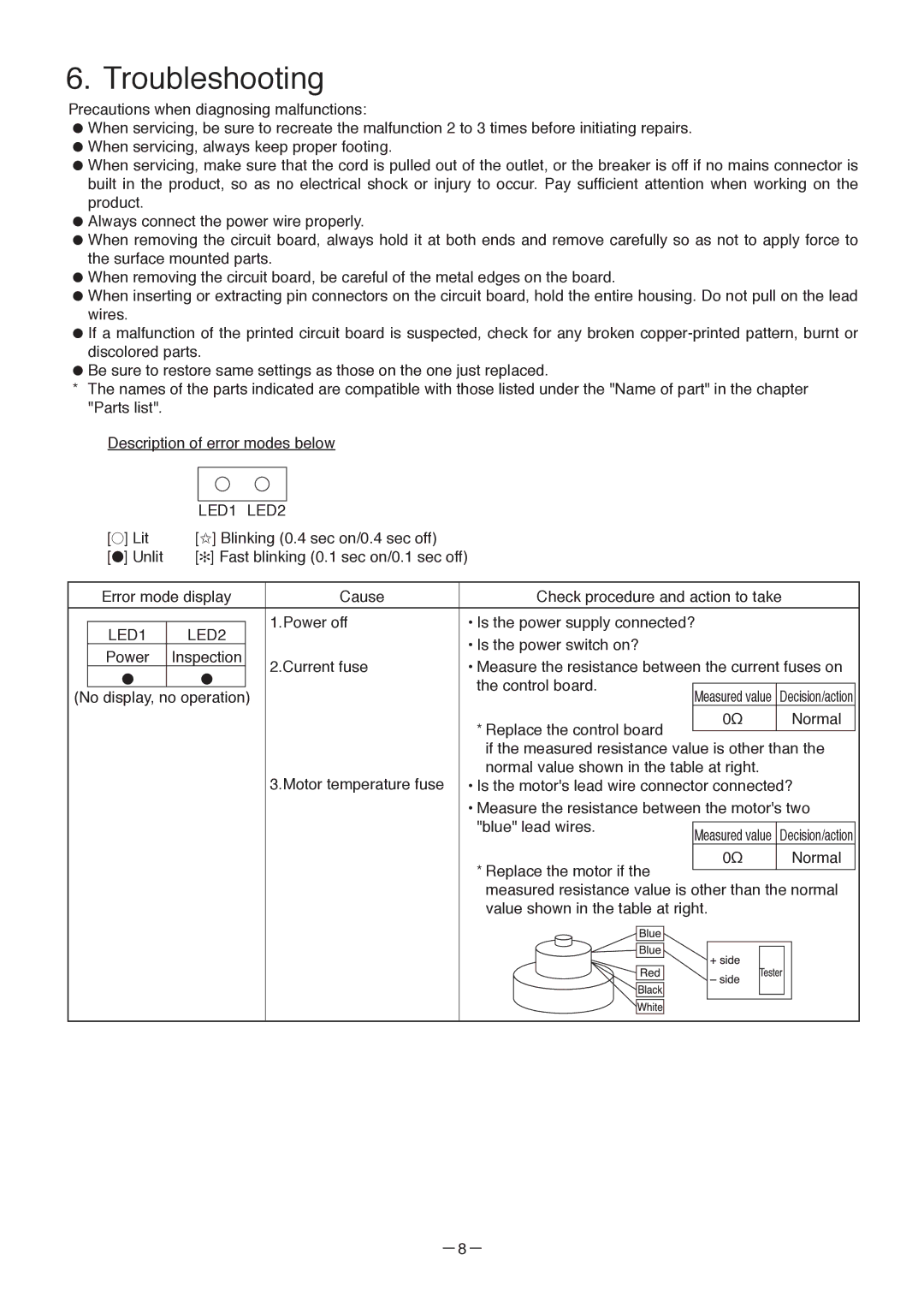
Description of error modes below
|
| LED1 LED2 |
|
|
|
|
|
|
| |||
| [●] Lit | [✩] Blinking (0.4 sec on/0.4 sec off) |
|
|
|
|
|
|
| |||
| [●] Unlit | [✻] Fast blinking (0.1 sec on/0.1 sec off) |
|
|
|
|
|
|
| |||
|
|
|
|
|
|
|
|
|
|
|
|
|
| Error mode display | Cause |
| Check procedure and action to take | ||||||||
|
|
|
|
|
|
|
|
| ||||
|
|
|
| 1.Power off |
| • Is the power supply connected? |
|
| ||||
| LED1 | LED2 |
|
|
| |||||||
|
|
|
| • Is the power switch on? |
|
|
|
|
| |||
| Power | Inspection |
|
|
|
|
|
|
|
| ||
|
| 2.Current fuse |
| • Measure the resistance between the current fuses on | ||||||||
| ● | ● |
|
| ||||||||
|
|
|
| the control board. |
|
|
|
|
| |||
(No display, no operation) |
|
| Measured value | Decision/action |
| |||||||
|
|
|
|
| ||||||||
|
|
|
|
|
| * Replace the control board |
|
| 0Ω | Normal |
| |
|
|
|
|
|
|
|
|
|
|
| ||
|
|
|
|
|
|
|
|
|
|
| ||
|
|
|
|
|
| if the measured resistance value is other than the | ||||||
|
|
|
| 3.Motor temperature fuse |
| normal value shown in the table at right. |
|
| ||||
|
|
|
|
| • Is the motor's lead wire connector connected? | |||||||
|
|
|
|
|
| • Measure the resistance between the motor's two | ||||||
|
|
|
|
|
| "blue" lead wires. |
|
|
|
|
| |
|
|
|
|
|
| Measured value | Decision/action |
| ||||
|
|
|
|
|
|
|
|
| ||||
|
|
|
|
|
| * Replace the motor if the |
|
| 0Ω | Normal |
| |
|
|
|
|
|
|
|
|
|
|
| ||
|
|
|
|
|
|
|
|
|
|
| ||
|
|
|
|
|
| measured resistance value is other than the normal | ||||||
|
|
|
|
|
| value shown in the table at right. |
|
| ||||
|
|
|
|
|
|
|
|
|
|
|
|
|
|
|
|
|
|
|
|
|
|
|
|
|
|
|
|
|
|
|
|
|
|
|
|
|
|
|
|
|
|
|
|
|
|
|
|
|
|
|
|
|
|
|
|
|
|
|
|
|
|
|
|
|
|
|
|
|
|
|
|
|
|
|
|
|
|
|
|
|
|
|
|
|
|
|
|
|
|
|
|
|
|
|
|
|
|
|
|
|
|
|
|