Controlling the Monitor with a PC (RS-232C)
RS-232C command table
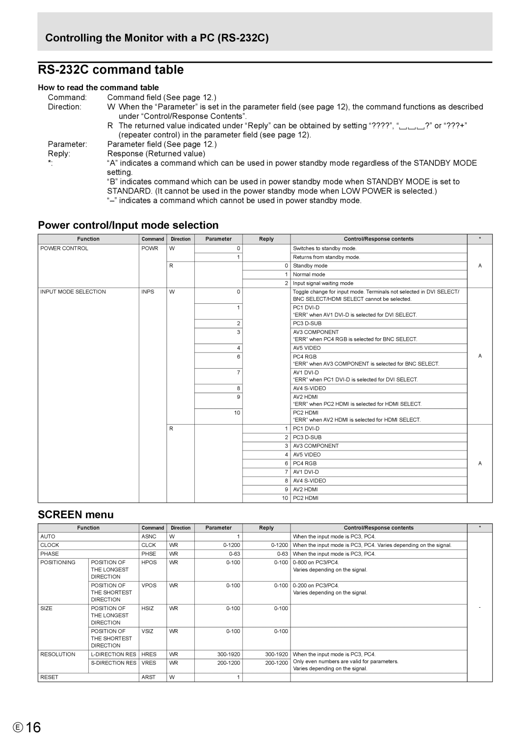
How to read the command table |
| |
Command: | Command field (See page 12.) |
|
Direction: | W When the “Parameter” is set in the parameter field (see page 12), the command functions as described | |
| under “Control/Response Contents”. |
|
| R The returned value indicated under “Reply” can be obtained by setting “????”, “ | ?” or “???+” |
| (repeater control) in the parameter field (see page 12). |
|
Parameter: | Parameter field (See page 12.) |
|
Reply: | Response (Returned value) |
|
*: | “A” indicates a command which can be used in power standby mode regardless of the STANDBY MODE | |
| setting. |
|
| “B” indicates command which can be used in power standby mode when STANDBY MODE is set to | |
| STANDARD. (It cannot be used in the power standby mode when LOW POWER is selected.) | |
|
| |
Power control/Input mode selection
Function | Command | Direction | Parameter |
| Reply | Control/Response contents | * |
|
|
|
|
|
|
|
|
POWER CONTROL | POWR | W |
| 0 |
| Switches to standby mode. |
|
|
|
|
|
|
|
|
|
|
|
|
| 1 |
| Returns from standby mode. |
|
|
|
|
|
|
|
|
|
|
| R |
|
| 0 | Standby mode | A |
|
|
|
|
|
|
|
|
|
|
|
|
| 1 | Normal mode |
|
|
|
|
|
|
|
|
|
|
|
|
|
| 2 | Input signal waiting mode |
|
|
|
|
|
|
|
|
|
INPUT MODE SELECTION | INPS | W |
| 0 |
| Toggle change for input mode. Terminals not selected in DVI SELECT/ |
|
|
|
|
|
|
| BNC SELECT/HDMI SELECT cannot be selected. |
|
|
|
|
|
|
|
|
|
|
|
|
| 1 |
| PC1 |
|
|
|
|
|
|
| “ERR” when AV1 |
|
|
|
|
|
|
|
|
|
|
|
|
| 2 |
| PC3 |
|
|
|
|
|
|
|
|
|
|
|
|
| 3 |
| AV3 COMPONENT |
|
|
|
|
|
|
| “ERR” when PC4 RGB is selected for BNC SELECT. |
|
|
|
|
|
|
|
|
|
|
|
|
| 4 |
| AV5 VIDEO |
|
|
|
|
|
|
|
| A |
|
|
|
| 6 |
| PC4 RGB | |
|
|
|
|
|
| “ERR” when AV3 COMPONENT is selected for BNC SELECT. |
|
|
|
|
|
|
|
|
|
|
|
|
| 7 |
| AV1 |
|
|
|
|
|
|
| “ERR” when PC1 |
|
|
|
|
|
|
|
|
|
|
|
|
| 8 |
| AV4 |
|
|
|
|
|
|
|
|
|
|
|
|
| 9 |
| AV2 HDMI |
|
|
|
|
|
|
| “ERR” when PC2 HDMI is selected for HDMI SELECT. |
|
|
|
|
|
|
|
|
|
|
|
|
| 10 |
| PC2 HDMI |
|
|
|
|
|
|
| “ERR” when AV2 HDMI is selected for HDMI SELECT. |
|
|
|
|
|
|
|
|
|
|
| R |
|
| 1 | PC1 |
|
|
|
|
|
|
|
|
|
|
|
|
|
| 2 | PC3 |
|
|
|
|
|
|
|
|
|
|
|
|
|
| 3 | AV3 COMPONENT |
|
|
|
|
|
|
|
|
|
|
|
|
|
| 4 | AV5 VIDEO |
|
|
|
|
|
|
|
|
|
|
|
|
|
| 6 | PC4 RGB | A |
|
|
|
|
|
|
|
|
|
|
|
|
| 7 | AV1 |
|
|
|
|
|
|
|
|
|
|
|
|
|
| 8 | AV4 |
|
|
|
|
|
|
|
|
|
|
|
|
|
| 9 | AV2 HDMI |
|
|
|
|
|
|
|
|
|
|
|
|
|
| 10 | PC2 HDMI |
|
|
|
|
|
|
|
|
|
SCREEN menu
| Function | Command | Direction | Parameter | Reply | Control/Response contents | * | |
|
|
|
|
|
|
|
|
|
AUTO |
|
| ASNC | W | 1 |
| When the input mode is PC3, PC4. |
|
|
|
|
|
|
|
|
|
|
CLOCK |
|
| CLCK | WR | When the input mode is PC3, PC4. Varies depending on the signal. |
| ||
|
|
|
|
|
|
|
|
|
PHASE |
|
| PHSE | WR | When the input mode is PC3, PC4. |
| ||
|
|
|
|
|
|
|
|
|
POSITIONING |
| POSITION OF | HPOS | WR |
| |||
|
| THE LONGEST |
|
|
|
| Varies depending on the signal. |
|
|
| DIRECTION |
|
|
|
|
|
|
|
|
|
|
|
|
|
|
|
|
| POSITION OF | VPOS | WR |
| |||
|
| THE SHORTEST |
|
|
|
| Varies depending on the signal. |
|
|
| DIRECTION |
|
|
|
|
|
|
|
|
|
|
|
|
|
| - |
SIZE |
| POSITION OF | HSIZ | WR |
| |||
|
|
| ||||||
|
| THE LONGEST |
|
|
|
|
|
|
|
| DIRECTION |
|
|
|
|
|
|
|
|
|
|
|
|
|
|
|
|
| POSITION OF | VSIZ | WR |
|
| ||
|
| THE SHORTEST |
|
|
|
|
|
|
|
| DIRECTION |
|
|
|
|
|
|
|
|
|
|
|
|
|
|
|
RESOLUTION |
| HRES | WR | When the input mode is PC3, PC4. |
| |||
|
|
|
|
|
|
| Only even numbers are valid for parameters. |
|
|
| VRES | WR |
| ||||
|
|
|
|
|
|
| Varies depending on the signal. |
|
|
|
|
|
|
|
|
|
|
RESET |
|
| ARST | W | 1 |
|
|
|
|
|
|
|
|
|
|
|
|
E16