7-3. Connecting the Sensors
•For channel 1, select one of the following four types: Pt100 detection, 4 to 20 mADC, 1 to 5 VDC, or 0 to 10 VDC analog input.
•For channel 2, select one of the following three types: 4 to 20 mADC, 1 to 5 VDC, or 0 to 10 VDC analog input.
•The wire length depends on the specifications of the sensor. However, since the use of long wires makes the device susceptible to noise, using wires shorter than 12 m (39.4 ft) is recommended. Use a shielded line for the sensor line and connect to the FG terminal on this unit or the FG terminal on the control panel.
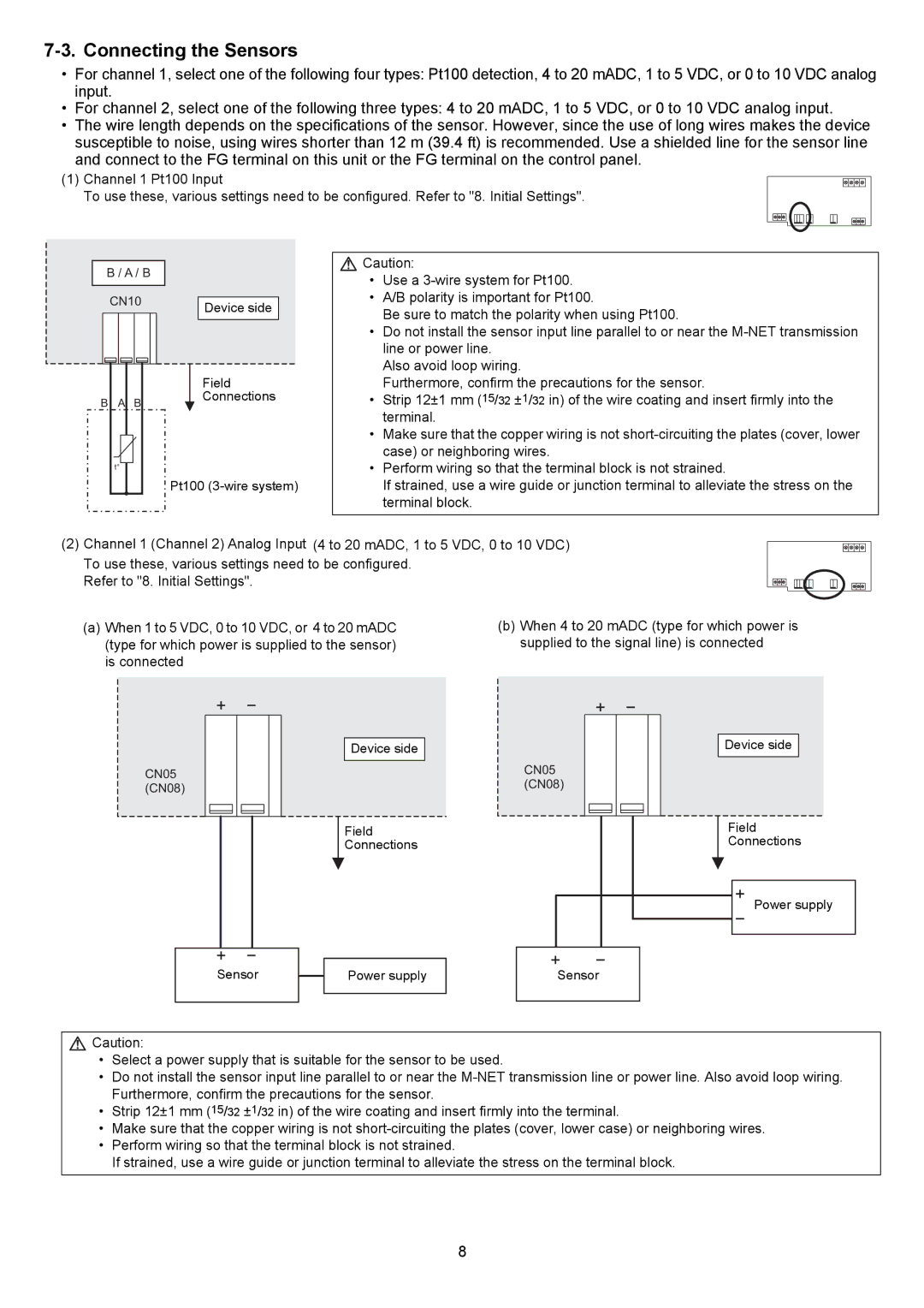
(1)Channel 1 Pt100 Input
To use these, various settings need to be configured. Refer to "8. Initial Settings".
B / A / B |
|
CN10 | Device side |
|
|
|
| Field |
B | A | B | Connections |
| |||
| t° |
|
|
|
|
| Pt100 |
![]() Caution:
Caution:
•Use a
•A/B polarity is important for Pt100.
Be sure to match the polarity when using Pt100.
•Do not install the sensor input line parallel to or near the
Also avoid loop wiring.
Furthermore, confirm the precautions for the sensor.
•Strip 12±1 mm (15/32 ±1/32 in) of the wire coating and insert firmly into the terminal.
•Make sure that the copper wiring is not
•Perform wiring so that the terminal block is not strained.
If strained, use a wire guide or junction terminal to alleviate the stress on the terminal block.
(2) Channel 1 (Channel 2) Analog Input (4 to 20 mADC, 1 to 5 VDC, 0 to 10 VDC)
To use these, various settings need to be configured. Refer to "8. Initial Settings".
(a)When 1 to 5 VDC, 0 to 10 VDC, or 4 to 20 mADC (type for which power is supplied to the sensor) is connected
(b)When 4 to 20 mADC (type for which power is supplied to the signal line) is connected
CN05
(CN08)
Device side
CN05
(CN08)
Field
Connections
Device side
Field
Connections
Power supply
Sensor
Power supply
Sensor
![]() Caution:
Caution:
•Select a power supply that is suitable for the sensor to be used.
•Do not install the sensor input line parallel to or near the
•Strip 12±1 mm (15/32 ±1/32 in) of the wire coating and insert firmly into the terminal.
•Make sure that the copper wiring is not
•Perform wiring so that the terminal block is not strained.
If strained, use a wire guide or junction terminal to alleviate the stress on the terminal block.
8