5Pair Number Setting
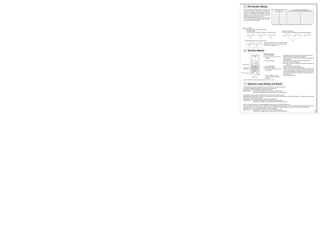
•Pair number setting is required to pair up a certain sig- nal receiving unit and a certain remote controller. This setting is not necessary unless assigning a particular indoor unit to a particular remote controller. (At factory shipment, the pair number on the signal receiving unit and wireless remote controller is set to “0.”)
•When this setting needs to be made, make the settings on the signal receiving unit and the wireless remote con- troller as shown in the right table.
Pair number setting on the wireless | In the case of CITY MULTI system |
remote controller | Set the pair number switch on the signal receiving unit. |
0 | 0 |
1 | 1 |
2 | 2 |
3 | 3 |
4 | 4 |
5 | 5 |
6 | 6 |
7 | 7 |
8 | 8 |
9 | 9 |
* Refer to the installation manual that comes with the signal receiving unit for details.
●Setting Example
(1)Controlling multiple units in the same room
•Individual setting
Each unit can be controlled from separate remote controllers.
•
All indoor units are controlled from a single remote controller.
| “0” | “1” | “2” | “0” | “0” | “0” |
|
|
|
| |||
|
|
|
|
|
| |
| “0” | “1” | “2” |
|
|
|
(2) Controlling multiple units in different rooms |
| “0” |
| |||
|
|
| ||||
|
|
| Set the signal receiving unit and wireless remote |
|
| |
|
|
|
|
| ||
| “0” | “0” | controller in the same room to the same number. |
|
| |
| (Use the factory setting as it is.) |
|
|
| ||
| “0” | “0” |
|
|
| |
|
|
|
|
| ||
|
|
|
|
|
|
|
6Test Run Method
| [Setting Procedures] | |||
| 1. | Turn on the power. | ||
TESTRUN | 2. | Press the | TEST RUN | button twice con- |
| ||||
|
|
|
| |
secutively.
3. Press the MODE button.
ON/OFF | TEMP |
* It will take three minutes after power on to start up the system. |
• TESTRUN and the operation setting will be displayed. |
• Make sure that the remote controller display indicates that the |
unit is stopped. |
• Operation mode will change to and from Cool and Heat. |
Cool: Confirm that cool air blows out. |
Heat: Confirm that warm air blows out (It takes a while for warm air |
ON/OFF button
FAN button MODE button
TEST RUN button
| FAN | AUTO STOP |
MODE | VANE | AUTO START |
CHECK | LOUVER | h |
TEST RUN |
| min |
SET | RESET CLOCK |
|
VANE button
4.Press the FAN button.
5.Press the VANE button.
6.Confirm that the outdoor unit fan is in operation.
7.Press the ON/OFF ![]() button
button
or press the TEST RUN button twice con- secutively.
to come out.) |
• Confirm that the fan speed changes. |
• Confirm the normal operation of |
• Outdoor unit controls its capacity by controlling the rotation speed |
of the fan. Depending on the outside air temperature, the fan runs |
at low speed and stays at the speed as long as it has enough |
power. Even if the fan stops or rotates in the reverse direction, it is |
not a malfunction. |
• Test run will be cancelled. |
•
7Operation Lamp Display and Buzzer
The following section details the operation lamp and the buzzer on the signal receiving unit. |
|
| |
<When receiving operation signals from the wireless remote controller> |
|
| |
Confirmation sound that indicates signal reception: Short beep |
|
| |
Operation lamp | During operation: Lights off three times at |
|
|
| While the unit is stopped: Lights up three times at |
|
|
<If a wireless remote controller is operated while the units are under centralized control> |
|
| |
Depending on the settings, when local control is prohibited by the centralized control system, ON/OFF, Mode selection, or Temperature setting buttons |
|
| |
on the remote controller may be disabled. |
|
| |
Confirmation sound that indicates signal reception: Two staccato beeps |
|
| |
Operation lamp | During operation: Lights off three times at |
|
|
| While the unit is stopped: Lights up three times at |
|
|
<When the preset temperature is corrected (Applicable to signal receiving unit |
|
| |
If the model setting on the wireless remote controller does not match the actual model type of the indoor unit that is connected, the signal receiving unit |
|
| |
will make correction on the preset temperature for the indoor unit. When this happens, signal receiving unit will perform the following actions. |
|
| |
Confirmation sound that indicates signal reception: Two staccato beeps |
|
| |
Operation lamp | During operation: Lights off three times at |
|
|
| While the unit is stopped: Lights up three times at | 7 |
|
|
|
| |