●Step 1
1.Check the model of the indoor unit to be controlled from the wireless remote controller.
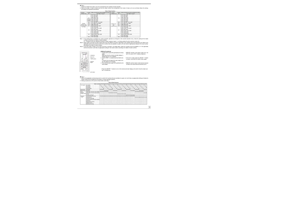
2.Refer to the table of model numbers and find the model number that corresponds to the model of indoor unit to be controlled. Make the settings according to the operation procedures.
Table of Model Numbers
Cooling/ | Model | Indoor unit model name (Only the prototypes are shown.) | Cooling/ | Model | Indoor unit model name (Only the prototypes are shown.) | |
heating Type | No. | CITY MULTI system | heating Type | No. | CITY MULTI system | |
|
|
|
|
| ||
|
|
|
|
| ||
| 001 |
|
| 033 | ||
|
|
| ||||
|
|
|
|
| ||
| Factory |
|
|
| ||
| setting |
|
|
| ||
|
|
|
| |||
|
|
|
|
| ||
| 002 |
|
| 034 | ||
Cooling/ | 009 |
| Cooling only | 041 | ||
Heating Type | 015 |
| 047 | |||
| type | |||||
(Cool/Dry/Auto/ | 017 |
| 049 | |||
| (Cool/Dry/Fan) | |||||
Fan/Heat) |
|
|
|
| ||
|
|
|
|
| ||
| 019 |
|
| 051 | ||
|
|
| ||||
|
|
|
|
| ||
|
|
|
|
| ||
|
|
|
|
| ||
| 020 |
|
| 052 | ||
|
|
|
|
| ||
| 023 |
|
| 055 | ||
Note 1: If the settings that are related to the remote controller operation are changed on the function selection menu, make the setting for the model number by referring to the table of model numbers.
(i.e., Changes to the vane adjustment setting (Function selection mode 11) or Swing setting (Function selection mode 23))
Note 2: Some indoor units with the same model name may have different functions, depending on the capacity type and production year. Refer to the applicable technical document to confirm the functions that are available to a given unit, and make an appropriate setting for the model number according to the table of model numbers.
Note 3: To set the model number for the indoor unit that is not listed in the table above, check the functions that are available to it in the applicable technical document, and make an appropriate setting for the model number according to the table of model numbers.
[Setting Procedures]
MODEL SELECT
Setting No.
![]()
![]() Model No.
Model No.
ON/OFF | TEMP | TEMP buttons |
|
|
1. | Push the SET button with a pointed but not sharp | |
| object. |
|
| Make sure that the remote controller display in- | |
| dicates that the unit is stopped. | |
2. | Use the TEMP | buttons to set the model num- |
| ber. |
|
| Functions that correspond to each model num- | |
• MODEL SELECT will blink, and model number “001” will |
be lit. (It is set to “001” at factory shipment.) |
• If an error is made, press the ON/OFF button |
to cancel, and enter the model number again. |
FAN AUTO STOP
MODE VANE AUTO START
ON/OFF button
ber will appear on the display. |
3. Press the set button again with a pointed but not |
sharp object. |
• MODEL SELECT and the model number that was entered |
will stay lit for three seconds and then go off. |
CHECK | LOUVER | h |
TEST RUN |
| min |
SET | RESET CLOCK |
|
SET button
•Press the ON/OFF ![]() button to turn on the remote controller display, and confirm that the model num- ber is correctly set.
button to turn on the remote controller display, and confirm that the model num- ber is correctly set.
AAA
AAA
●Step 2
1.Refer to the applicable technical document to confirm the functions that are available to a given unit, and make an appropriate setting by finding the model number that corresponds to the pattern of those available functions.
2.Setting procedures are the same for those listed under Step 1.
Table of Model Numbers
| Model number | 001 | 002 | 003 | 004 | 005 | 006 | 007 | 008 | 009 | 010 | 011 | 012 | 013 | 014 | 015 | 016 | 017 | 018 | 019 | 020 | 021 | 022 | 023 | 024 | 025 | 026 | 027 | 028 | 029 | 030 | 031 | 032 | 033 | 034 | 035 | 036 | 037 | 038 | 039 | 040 | 041 | 042 | 043 |
1.Fan speed | 14 speeds |
|
|
|
|
|
|
|
|
|
|
|
|
|
|
|
|
|
|
|
|
|
|
|
|
|
|
|
|
|
|
|
|
|
|
|
|
|
|
|
|
|
|
|
| 23 speeds |
|
|
|
|
|
|
|
|
|
|
|
|
|
|
|
|
|
|
|
|
|
|
|
|
|
|
|
|
|
|
|
|
|
|
|
|
|
|
|
|
|
|
|
| 32 speeds |
|
|
|
|
|
|
|
|
|
|
|
|
|
|
|
|
|
|
|
|
|
|
|
|
|
|
|
|
|
|
|
|
|
|
|
|
|
|
|
|
|
|
|
| 4Fixed speed |
|
|
|
|
|
|
|
|
|
|
|
|
|
|
|
|
|
|
|
|
|
|
|
|
|
|
|
|
|
|
|
|
|
|
|
|
|
|
|
|
|
|
|
2.Louver swing | 1Disabled |
|
|
|
|
|
|
|
|
|
|
|
|
|
|
|
|
|
|
|
|
|
|
|
|
|
|
|
|
|
|
|
|
|
|
|
|
|
|
|
|
|
|
|
(horizontal air | 2Enabled |
|
|
|
|
|
|
|
|
|
|
|
|
|
|
|
|
|
|
|
|
|
|
|
|
|
|
|
|
|
|
|
|
|
|
|
|
|
|
|
|
|
|
|
direction control) |
|
|
|
|
|
|
|
|
|
|
|
|
|
|
|
|
|
|
|
|
|
|
|
|
|
|
|
|
|
|
|
|
|
|
|
|
|
|
|
|
|
|
| |
3.Vane | 1Adjustable vane/Auto swing enabled |
|
|
|
|
|
|
|
|
|
|
|
|
|
|
|
|
|
|
|
|
|
|
|
|
|
|
|
|
|
|
|
|
|
|
|
|
|
|
|
|
|
|
|
(vertical air | 2Adjustable vane/Auto swing disabled |
|
|
|
|
|
|
|
|
|
|
|
|
|
|
|
|
|
|
|
|
|
|
|
|
|
|
|
|
|
|
|
|
|
|
|
|
|
|
|
|
|
|
|
direction control) | 3Fixed |
|
|
|
|
|
|
|
|
|
|
|
|
|
|
|
|
|
|
|
|
|
|
|
|
|
|
|
|
|
|
|
|
|
|
|
|
|
|
|
|
|
|
|
| 4Undefined (Fixed) |
|
|
|
|
|
|
|
|
|
|
|
|
|
|
|
|
|
|
|
|
|
|
|
|
|
|
|
|
|
|
|
|
|
|
|
|
|
|
|
|
|
|
|
4.Operation | 1Cool/Dry/Auto/Fan/Heat |
|
|
|
|
|
|
|
|
|
|
|
|
|
|
|
|
|
|
|
|
|
|
|
|
|
|
|
|
|
|
|
|
|
|
|
|
|
|
|
|
|
|
|
mode | 2Cool/Dry/Fan |
|
|
|
|
|
|
|
|
|
|
|
|
|
|
|
|
|
|
|
|
|
|
|
|
|
|
|
|
|
|
|
|
|
|
|
|
|
|
|
|
|
|
|
|
|
|
|
|
|
|
|
|
|
|
|
|
|
|
|
|
|
|
|
|
|
|
|
|
|
|
|
|
|
|
|
|
|
|
|
|
|
|
|
|
|
|
| |
| 3Cool/Dry/Auto/Heat |
|
|
|
|
|
|
|
|
|
|
|
|
|
|
|
|
|
|
|
|
|
|
|
|
|
|
|
|
|
|
|
|
|
|
|
|
|
|
|
|
|
|
|
| 4Cool/Dry/Auto/Fan/Combustion Heat/Heat |
|
|
|
|
|
|
|
|
|
|
|
|
|
|
|
|
|
|
|
|
|
|
|
|
|
|
|
|
|
|
|
|
|
|
|
|
|
|
|
|
|
|
|
| 5Cool/Fan |
|
|
|
|
|
|
|
|
|
|
|
|
|
|
|
|
|
|
|
|
|
|
|
|
|
|
|
|
|
|
|
|
|
|
|
|
|
|
|
|
|
|
|
| 6Cool/Auto/Fan/Heat |
|
|
|
|
|
|
|
|
|
|
|
|
|
|
|
|
|
|
|
|
|
|
|
|
|
|
|
|
|
|
|
|
|
|
|
|
|
|
|
|
|
|
|
| 7Cool/Fan/Heat |
|
|
|
|
|
|
|
|
|
|
|
|
|
|
|
|
|
|
|
|
|
|
|
|
|
|
|
|
|
|
|
|
|
|
|
|
|
|
|
|
|
|
|
| 8Cool/Dry/Fan/Heat |
|
|
|
|
|
|
|
|
|
|
|
|
|
|
|
|
|
|
|
|
|
|
|
|
|
|
|
|
|
|
|
|
|
|
|
|
|
|
|
|
|
|
|
3