Conditions | Action of the signal receiving unit |
Reception of a signal from the wireless remote controller | The temperature setting will be corrected to the maximum or minimum settable temperature and set to the |
that corresponds to a preset temperature that is outside of | indoor unit. |
the setting range | Example: When the setting range for the cooling operation of the indoor unit is between 19 °C and 30 °C |
| and the signal to set the cooling temperature to 17 °C is received from the wireless remote controller. |
| (Action) The signal receiving unit will read the temperature as 19 °C and set it to the indoor unit.) |
Reception of a signal from the wireless remote controller | |
that corresponds to an even numbered temperature setting | and set to the indoor unit. |
in Fahrenheit when the connected indoor unit is not | Example: Reception of a signal that corresponds to 78 °F when the connected indoor unit is not compatible |
compatible with temperature setting in 1 °F increments. | with temperature setting in 1 °F increments. |
| (Action) The signal receiving unit will read 78 °F as 77 °F and set it to the indoor unit.) |
<In case of a problem>
Operation lamp will blink, indicating a problem with the air conditioner. When this happens, turn off the power to the air conditioner, and consult your dealer. Do not attempt to repair the unit by yourself.
<Making a self-diagnosis>
Refer to section 8
<Operating the emergency operation button on the signal receiving unit>
Confirmation sound that indicates signal reception: None
Operation lamp | During operation: Unlit |
| While the unit is stopped: Lit |
| When local control is prohibited, remote controller will be disabled. |
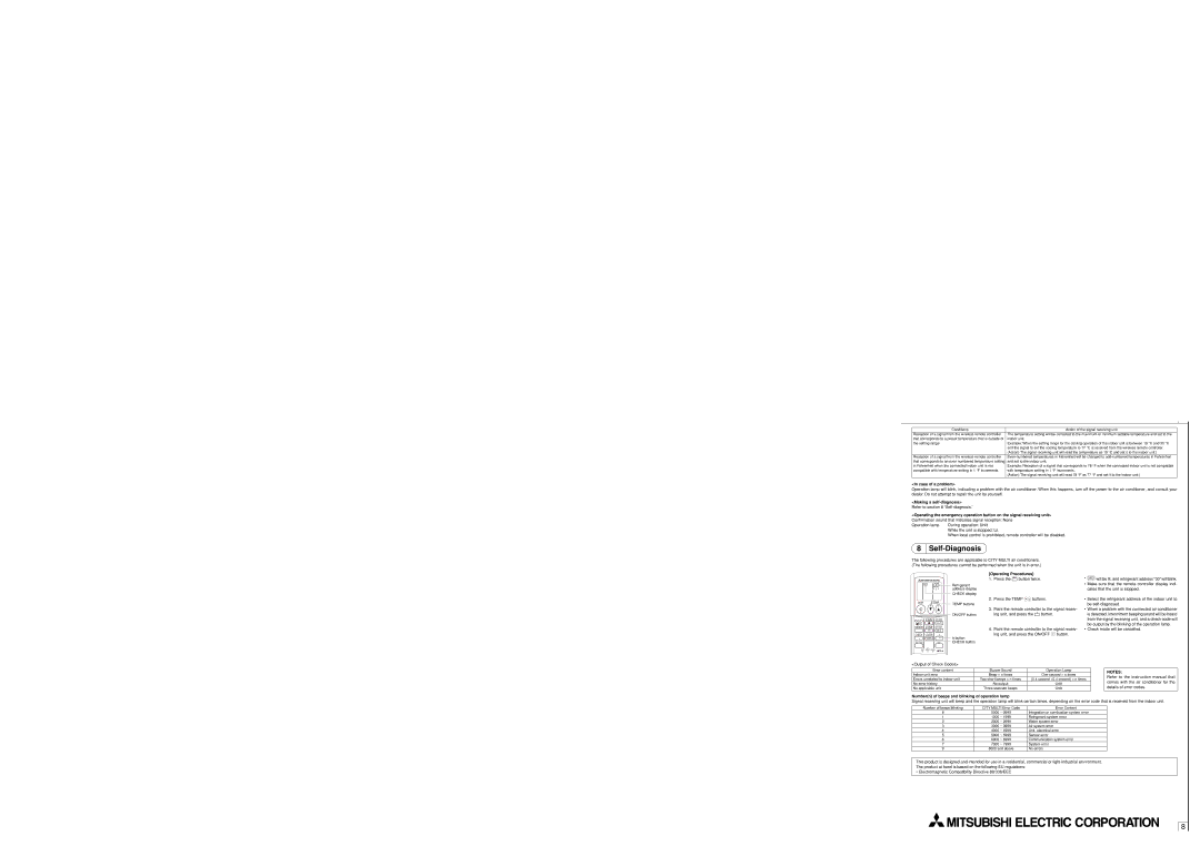
8Self-Diagnosis
The following procedures are applicable to CITY MULTI air conditioners. (The following procedures cannot be performed when the unit is in error.)
CHECK
ON/OFF ![]() TEMP
TEMP
FAN AUTO STOP
MODE VANE AUTO START
CHECK | LOUVER | h |
TEST RUN |
| min |
Refrigerant address display
CHECK display
TEMP buttons
ON/OFF button
hbutton CHECK button
[Operating Procedures]
1.Press the CHECK button twice.
2.Press the TEMP ![]()
![]() buttons.
buttons.
3.Point the remote controller to the signal receiv- ing unit, and press the h button.
4.Point the remote controller to the signal receiv- ing unit, and press the ON/OFF ![]() button.
button.
*CHECK will be lit, and refrigerant address “00” will blink.
• Make sure that the remote controller display indi- cates that the unit is stopped.
•Select the refrigerant address of the indoor unit to be
•When a problem with the connected air conditioner is detected, intermittent beeping sound will be heard from the signal receiving unit, and a check code will be output by the blinking of the operation lamp.
•Check mode will be cancelled.
SET RESET CLOCK
<Output of Check Codes>
Error content | Buzzer Sound | Operation Lamp |
Indoor unit error | Beep ⋅ n times | One second ⋅ n times |
Errors unrelated to indoor unit | Two short beeps ⋅ n times | (0.4 second +0.4 second) ⋅ n times |
No error history | No output | Unlit |
No applicable unit | Three staccato beeps | Unlit |
|
|
|
Number(n) of beeps and blinking of operation lamp
NOTES:
Refer to the instruction manual that comes with the air conditioner for the details of error codes.
Signal receiving unit will beep and the operation lamp will blink certain times, depending on the error code that is received from the indoor unit.
Number of beeps/blinking | CITY MULTI Error Code | Error Content |
8 | 0000 ~ 0999 | Integration or combustion system error |
1 | 1000 ~ 1999 | Refrigerant system error |
2 | 2000 ~ 2999 | Water system error |
3 | 3000 ~ 3999 | Air system error |
4 | 4000 ~ 4999 | Unit, electrical error |
5 | 5000 ~ 5999 | Sensor error |
6 | 6000 ~ 6999 | Communication system error |
7 | 7000 ~ 7999 | System error |
9 | 8000 and above | No errors |
This product is designed and intended for use in a residential, commercial or
The product at hand is based on the following EU regulations:
• Electromagnetic Compatibility Directive 89/336/EEC
8
