1. Television Overview | 9 |
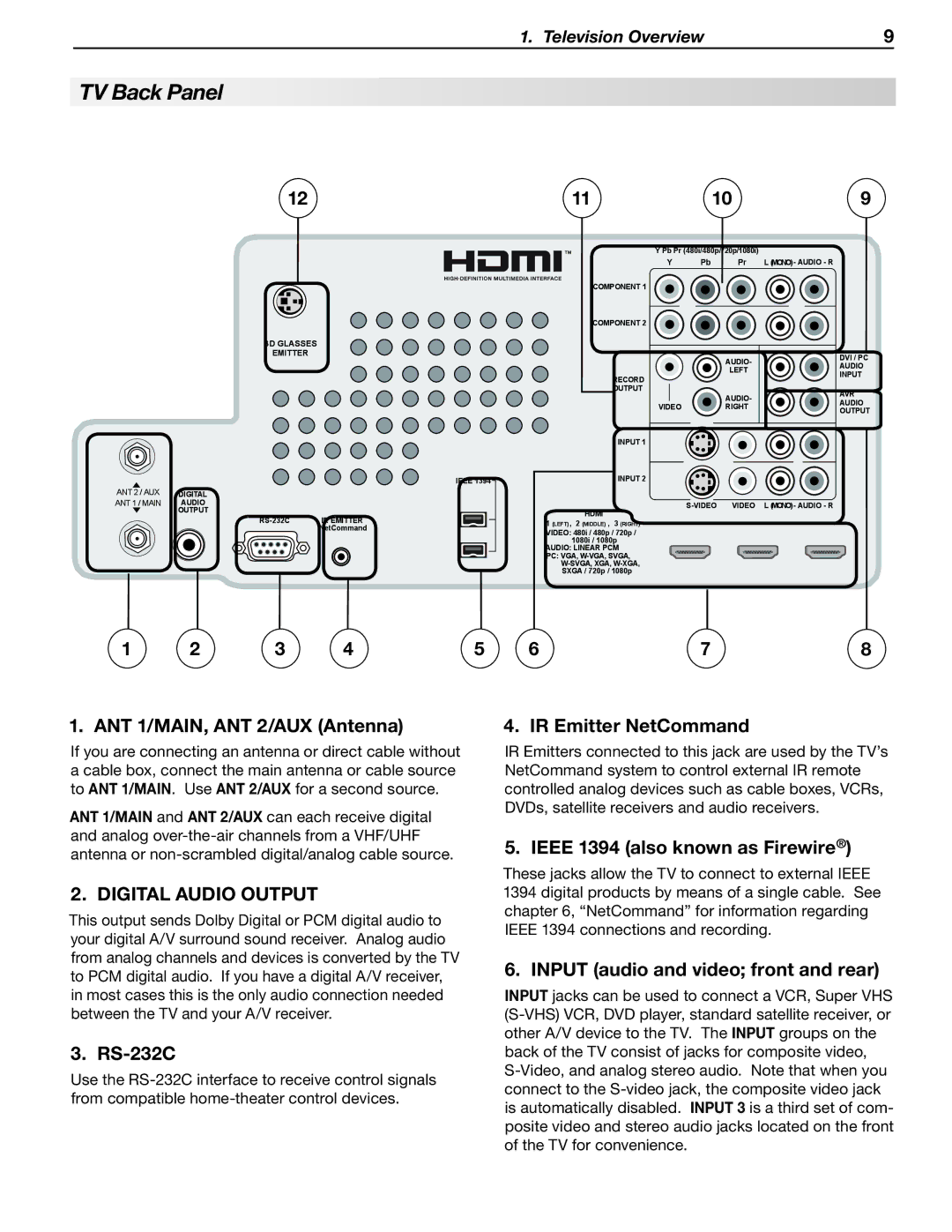
TV Back Panel
12 | 11 | 10 | 9 |
3D GLASSES
EMITTER
IEEE 1394
ANT 2 / AUX | DIGITAL |
ANT 1 / MAIN | AUDIO |
| OUTPUT |
IR EMITTER | |
| NetCommand |
COMPONENT 1
COMPONENT 2
RECORD
OUTPUT
INPUT 1
INPUT 2
HDMI
1 (LEFT) , 2 (MIDDLE) , 3 (RIGHT)
VIDEO: 480i / 480p / 720p / 1080i / 1080p
AUDIO: LINEAR PCM
PC: VGA,
Y Pb Pr (480i/480p/720p/1080i)
Y | Pb | Pr | L (MONO)- AUDIO - R | ||
|
|
|
|
|
|
AUDIO-
LEFT
AUDIO-
VIDEORIGHT
|
|
|
|
|
VIDEO L (MONO)- AUDIO - R | ||||
DVI / PC AUDIO INPUT
AVR AUDIO OUTPUT
1 | 2 | 3 | 4 | 5 |
6 | 7 | 8 |
1. ANT 1/MAIN, ANT 2/AUX (Antenna)
If you are connecting an antenna or direct cable without a cable box, connect the main antenna or cable source to ANT 1/MAIN. Use ANT 2/AUX for a second source.
ANT 1/MAIN and ANT 2/AUX can each receive digital and analog
2. DIGITAL AUDIO OUTPUT
This output sends Dolby Digital or PCM digital audio to your digital A/V surround sound receiver. Analog audio from analog channels and devices is converted by the TV to PCM digital audio. If you have a digital A/V receiver, in most cases this is the only audio connection needed between the TV and your A/V receiver.
3. RS-232C
Use the
4. IR Emitter NetCommand
IR Emitters connected to this jack are used by the TV’s NetCommand system to control external IR remote controlled analog devices such as cable boxes, VCRs, DVDs, satellite receivers and audio receivers.
5. IEEE 1394 (also known as Firewire®)
These jacks allow the TV to connect to external IEEE 1394 digital products by means of a single cable. See chapter 6, “NetCommand” for information regarding IEEE 1394 connections and recording.
6. INPUT (audio and video; front and rear)
Input jacks can be used to connect a VCR, Super VHS