Connecting VCR Video and Audio to an Antenna or Wall Outlet Cable

VCR to Antenna or Wall Outlet Cable

Figure 5

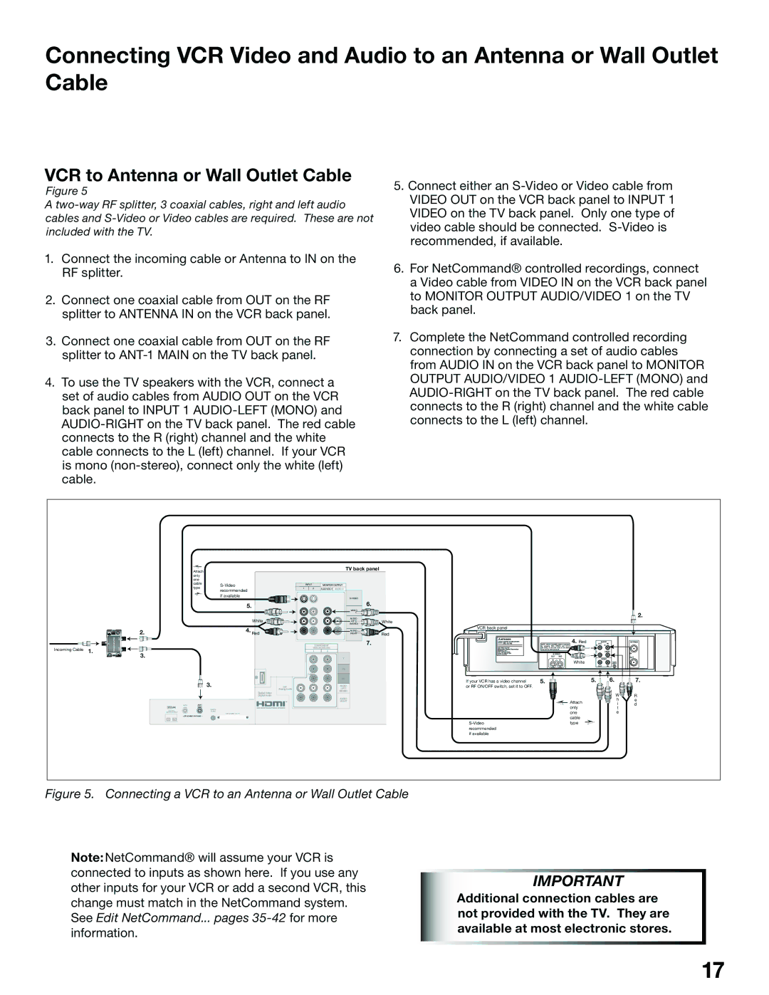
A two-way RF splitter, 3 coaxial cables, right and left audio cables and S-Video or Video cables are required. These are not included with the TV.

1.Connect the incoming cable or Antenna to IN on the RF splitter.

2.Connect one coaxial cable from OUT on the RF splitter to ANTENNA IN on the VCR back panel.

3.Connect one coaxial cable from OUT on the RF splitter to ANT-1 MAIN on the TV back panel.

4.To use the TV speakers with the VCR, connect a set of audio cables from AUDIO OUT on the VCR back panel to INPUT 1 AUDIO-LEFT (MONO) and AUDIO-RIGHT on the TV back panel. The red cable connects to the R (right) channel and the white cable connects to the L (left) channel. If your VCR is mono (non-stereo), connect only the white (left) cable.

5.Connect either an S-Video or Video cable from VIDEO OUT on the VCR back panel to INPUT 1 VIDEO on the TV back panel. Only one type of video cable should be connected. S-Video is recommended, if available.

6.For NetCommand® controlled recordings, connect a Video cable from VIDEO IN on the VCR back panel to MONITOR OUTPUT AUDIO/VIDEO 1 on the TV back panel.

7.Complete the NetCommand controlled recording connection by connecting a set of audio cables from AUDIO IN on the VCR back panel to MONITOR OUTPUT AUDIO/VIDEO 1 AUDIO-LEFT (MONO) and AUDIO-RIGHT on the TV back panel. The red cable connects to the R (right) channel and the white cable connects to the L (left) channel.


Attach


only


one


cable

S-Video


type


recommended


if available


5.


White

2.


4. Red

TV back panel

INPUT


MONITOR OUTPUT


1


2

AUDIO/VIDEO 1

AUDIO 2


S-VIDEO


6.

VIDEO


AUDIO-

White

(MONO)

LEFT/


AUDIO-

Red

RIGHT

2.

VCR back panel

IN

SPLITTER

OUT


WAY


COMPONENT

7.

HS-U748

4. Red

Incoming Cable 1.

TWO

OUT


3.

YPbPr (480i/480p/1080i)

1 2

TUBE

R

Y

Pb

Pr

White


5.

6.

7.


3.

DVI


Analog Audio


Digital Video


Digital Audio

ANT-2

ANT-1


AUX

MAIN


IEEE1394

DIGITAL


INPUT/OUTPUT

AUDIO


CableCARD

SLOT

– (DTV/CABLE /VHF/UHF)


AUDIO-

LEFT/

(MONO)

AUDIO- RIGHT

If your VCR has a video channel

5.


or RF ON/OFF switch, set it to OFF.


W

R


Attach

h

e


i

d


only

t


one

e


cable


S-Video

type


recommended


if available


Figure 5. Connecting a VCR to an Antenna or Wall Outlet Cable

Note:NetCommand® will assume your VCR is connected to inputs as shown here. If you use any other inputs for your VCR or add a second VCR, this change must match in the NetCommand system. See Edit NetCommand... pages 35-42for more information.

IMPORTANT

Additional connection cables are not provided with the TV. They are available at most electronic stores.

17

Page 17
Image 17
Mitsubishi Electronics WS-55815, WS-65815 manual VCR to Antenna or Wall Outlet Cable, Red

WS-55815, WS-65815 specifications

The Mitsubishi Electronics WS-65815 and WS-55815 are high-quality rear-projection televisions that gained popularity in the early 2000s for their impressive display performance and advanced features. These models were designed to provide an immersive viewing experience, highlighting Mitsubishi's commitment to innovation in the home entertainment market.

One of the standout features of the WS-65815 and WS-55815 is their large screen sizes. The WS-65815 offers a massive 65-inch display, while the WS-55815 comes in at 55 inches. Both models utilize a DLP (Digital Light Processing) technology that delivers exceptional picture quality with vibrant colors and sharp details. DLP technology also contributes to deeper blacks and a higher contrast ratio, enhancing the overall visual experience.

Mitsubishi incorporated a 16:9 aspect ratio in both models, which is ideal for watching widescreen content, such as movies and sports events. The advanced color wheel in these televisions enhances the saturation and chromatic accuracy of the images displayed. Additionally, both models support 1080p resolution, making them compatible with high-definition broadcasts and Blu-ray Disc viewing, ensuring users can enjoy stunning picture clarity.

Another key characteristic of the WS-65815 and WS-55815 is their integrated video processing technology. The units feature a built-in 3D Y/C digital comb filter that significantly improves image quality by reducing artifacts and enhancing detail resolution. The televisions also offer multiple input options, including HDMI and component video, allowing users to connect various devices such as gaming consoles, cable boxes, and DVD players seamlessly.

The design of both models is characterized by a sleek cabinet finish, which allows them to blend seamlessly into modern home décor. Furthermore, the televisions are equipped with a user-friendly remote control with programmable features, enabling easy navigation through channels, inputs, and settings.

In summary, the Mitsubishi Electronics WS-65815 and WS-55815 rear-projection televisions stood out for their impressive screen size, advanced DLP technology, and rich, immersive picture quality. These models remain noteworthy examples of Mitsubishi’s innovation in television technology, making them desirable among enthusiasts even in today’s evolving market.